故障排除Troubleshooting.pdf - 第18页
Page 16 52489101 Rev . B IM T roubleshooting This document supports Radial 88, VCD Seq 88, and Jumper Wire 88 machines. Troubleshooting Table - Feeder(Radial Only) The following table lists possible error scenarios for f…
Page 15
IM Troubleshooting 52489101 Rev. B
This document supports Radial 88, VCD Seq 88, and Jumper Wire 88 machines.
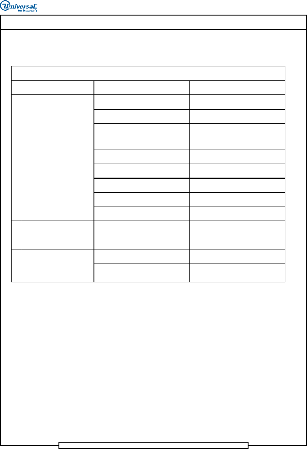
Troubleshooting Table - Process Errors
The following table lists possible error scenarios for process errors.
Probable Ca use Correc tive Action
Software not initialized.
Reboot the system. Refer to IM-UPS
manual.
Product not loaded. Load product. Refer to IM-UPS manual.
Machine Status message indicates low air,
or required home, clear, or in position
swi tch is n ot made.
Refer to maintenance manual, adjust
switch or air as required.
Anvil home (VCD and Jumper Wire) or
clinch down (Radial) swi tch failed.
Refer to maintenance procedures and
adjust or replace anvil home switch.
Rotary table in position switch failed.
Refer to maintenance procedures and
adjust or replace in position switch.
Board count at zero or not entered in
prog ram.
Enter a new board count at the machine
terminal.
Faulty START push button or related
circuitry.
Use diagnostics to check START switch
circuitry.
Rear Stop button latched. Unlatch rear Stop button.
Failed 32 DC ou tput PCB. Repla ce faulty PCB.
Faulty lamps.
Replace lamps. Refer to electrical system
table.
During the zeroing process, an axis goes
into a limit error.
Activate the ZERO function.
If after comple tin g the above step the
LIMIT condition is still activated, indicates
an axis
p
roblem.
Refer to X-Y positioning system table or
component transfer table respectively.
Troubleshooting Table - Process Errors
1
Indicated Trouble
Machine power up but does not
start.
No control panel indicators on.
2
3
LIMIT condition activated.
Page 16
52489101 Rev. B IM Troubleshooting
This document supports Radial 88, VCD Seq 88, and Jumper Wire 88 machines.
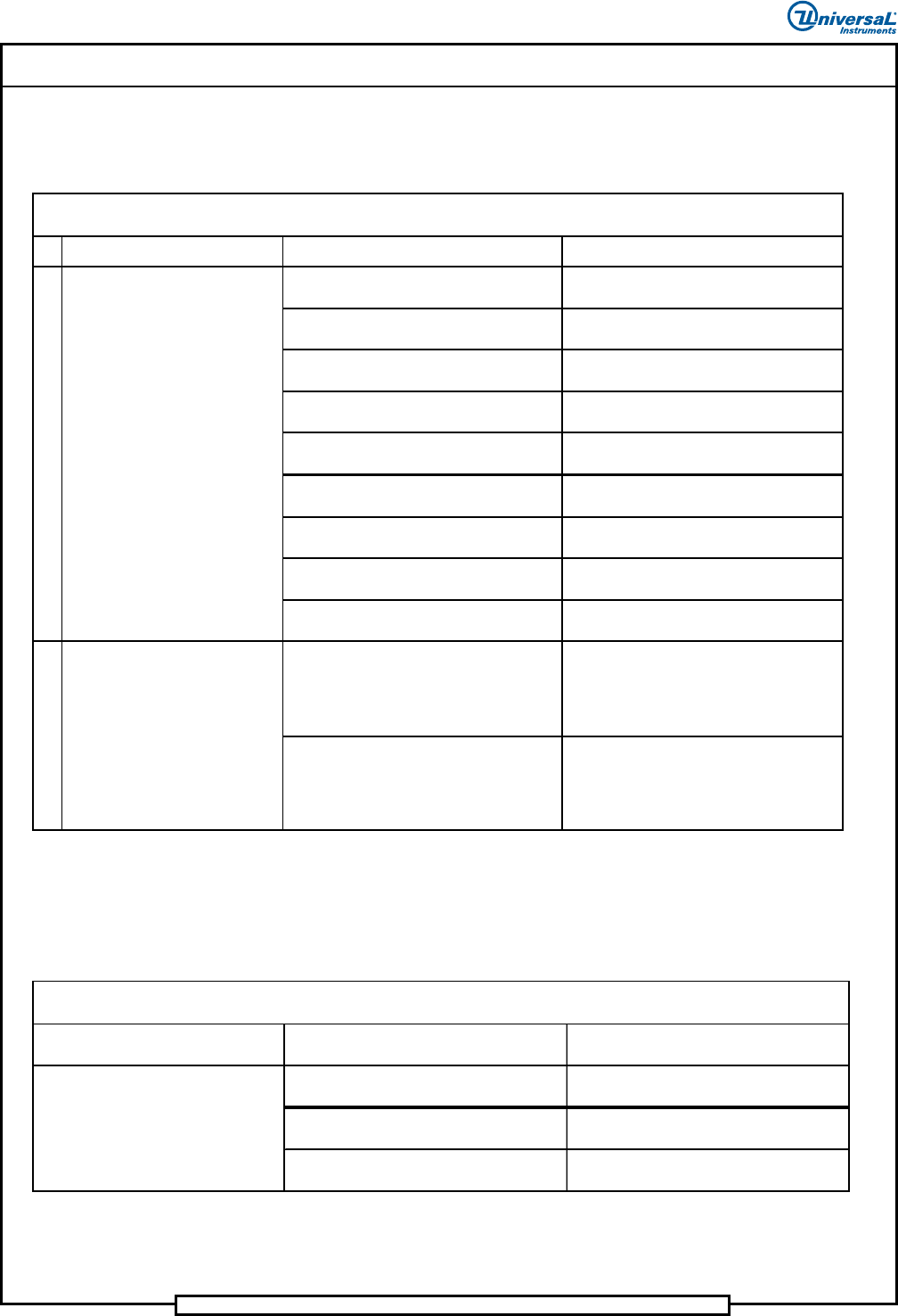
Troubleshooting Table - Feeder(Radial Only)
The following table lists possible error scenarios for feeder errors.
Indicated Trouble Probable Cause Corrective Action
Dispensing head out of components. Load components.
Component carrier tape damaged.
Cut out damaged area and splice
component tape back together.
Dispenser head to carrier clip out of
alignment.
Adjust per maintenance manual.
Incorrect ratchet wheel adjustment. Adjust per maintenance manual.
Incorrect cutter gap adjustment. Adjust per maintenance manual.
Incorrect cylinder stroke adjustment. Adjust per maintenance manual.
Failed drive cylinder, control valve or
solenoid.
Replace failed part.
Failed 16AC Out PC board. Replace failed PC board.
Head not plugged in or plugged into wrong
con nector.
Plug head into correct connector.
Emitter/receiver sensor alignment to feeder
out of specification.
Adjust per Maintenance Manual.
Slow acting feeder.
Clean and lubricate per Preventive
Maintenance instructions.
Components not transferring
to carri er clip
Troubleshooting Table - Feeder
1
Component has been
succe ssfully transferred to the
carrier clip, but the machine stops
with one of the following error
messages displayed:
• Machine waiting for dispensing
head extend
• Machine waiting for dispensing
head retracted
2
Troubleshooting Table - Cutter Station (Radial Only)
The following table lists possible error scenarios for cutter station errors.
Indicated Trouble Probable Cause Corrective Action
Cutter station is out of adjustment.
Adjust per maintenance manual
(Sequencer section).
Failed 32 DC Out PC board. Replace failed PC board.
Damaged pull down fingers. Inspect and replace if necessary.
Carrier tape is not cut or is
improperly cut.
Troubleshooting Table - Cutter Station Errors
Page 17
IM Troubleshooting 52489101 Rev. B
This document supports Radial 88, VCD Seq 88, and Jumper Wire 88 machines.
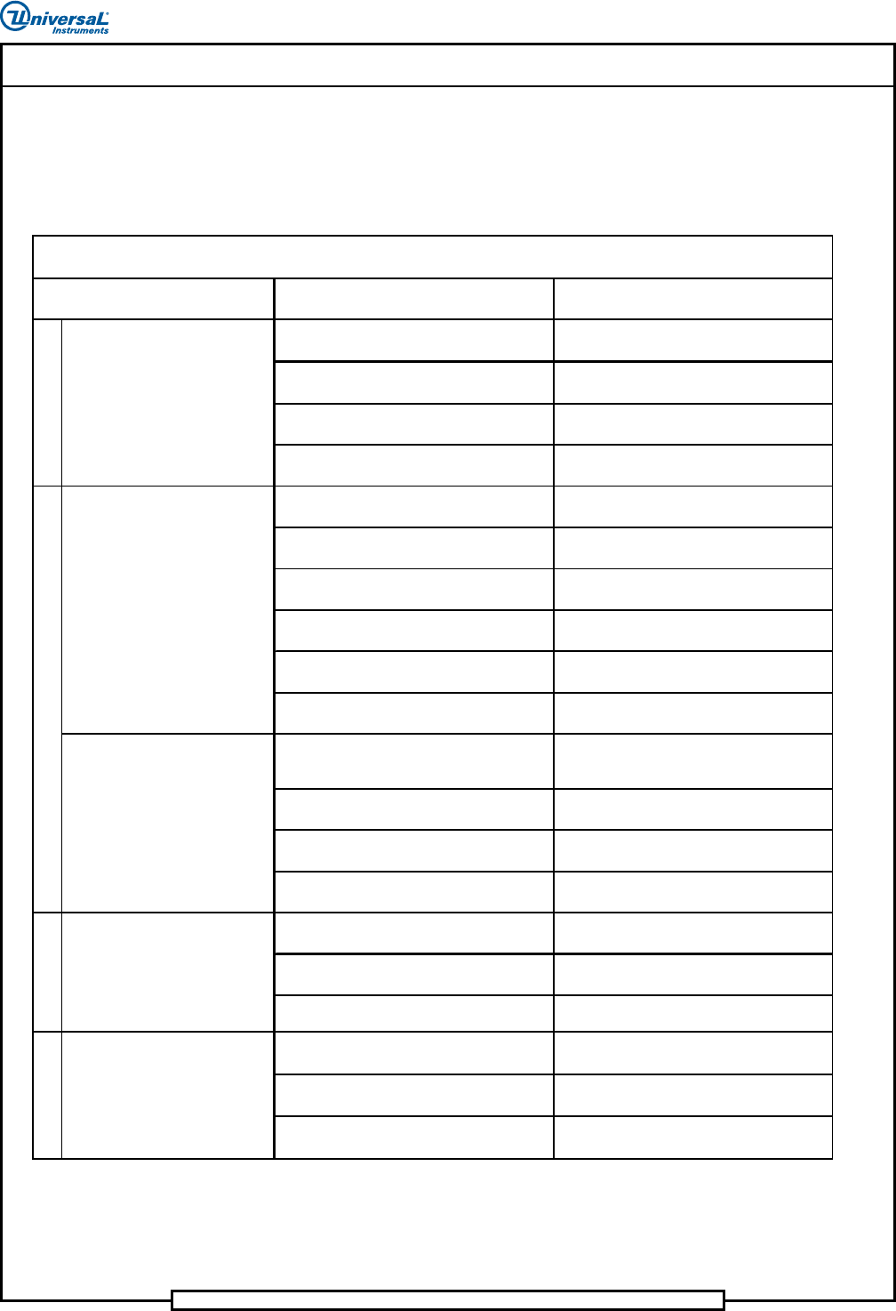
Troubleshooting Table - Component Transfer Errors
(VCD and Radial Only)
The following table lists possible error scenarios for component transfer
errors.
Probable Cause Corrective Action
Refire error. Check refire board and optical sensor.
Dispensing head not adj usted for
component type.
Adjust dispensing head as required.
Faulty MMIT I/O board. Replace faulty board.
Worn or leaky air cylinder on a particular
feeder.
Replace seals on cylinder.
Chain misaligned or dispensing head pitch
wheels incorrectly set.
Check chain alignment or adjust
dispensing head pitch wheels.
Input components binding. Check component input and clear binding.
Drop timing improperly set. Correct drop timing and reset as required.
Chain to chain transfer not properly set.
Check chain to chain and adjust as
re quired.
Refire malfunctioning or disabled.
Repair, replace or enable refire as
re quired.
Worn or leaky air cylinder on a particular
feeder.
Replace seals on cylinder.
Spans are increasing more than .300 inch
(7,6mm) between pattern steps.
Reprogram pattern steps to eliminate span
increases more than .300 in. (7,6mm).
Shear blocks edges are dull. Replace shear blocks.
Broken or worn compression springs in
chain clips.
Replace faulty compression springs.
Worn chain clips. Repla ce faulty chain clips.
Home pulse not generated, encoder failed.
Refer to maintenance procedures and
re place encoder.
Home pulse not detected. Motion control
board failed.
Refer to maintenance procedures and
re place motion control board.
Faulty limit switch or wiring.
Troubleshoot wiring or replace faulty
switch.
Transfer stroke is too long or short.
Adjust CTA to head stroke per
maintenance manual.
CTA latch timing adjustment/worn or
broken spring .
Adjust timing per maintena nce man ual/
re place spring.
CTA is not aligned with the insertion head.
Align CTA to head per maintenance
manual.
4
Troubleshooting Table - Component Transfer Errors
VCD only:
Two or more components in one
sequencer chain position.
1
VCD only:
Components intermittently
missing from sequence.
Indicated Trouble
5
VCD only:
Scrap leads falling out of chain
clips.
VCD only:
Head chain goes into limit error
when START is pushed.
Radial only:
Component leads are bent.
2
3