故障排除Troubleshooting.pdf - 第6页
Page 4 52489101 Rev . B IM T roubleshooting This document supports Radial 88, VCD Seq 88, and Jumper Wire 88 machines. 7. While the centering assembly centers a component two positions before the insertion position, the …
Page 3
IM Troubleshooting 52489101 Rev. B
This document supports Radial 88, VCD Seq 88, and Jumper Wire 88 machines.
Pneumatic Valve Actuators
Plunger
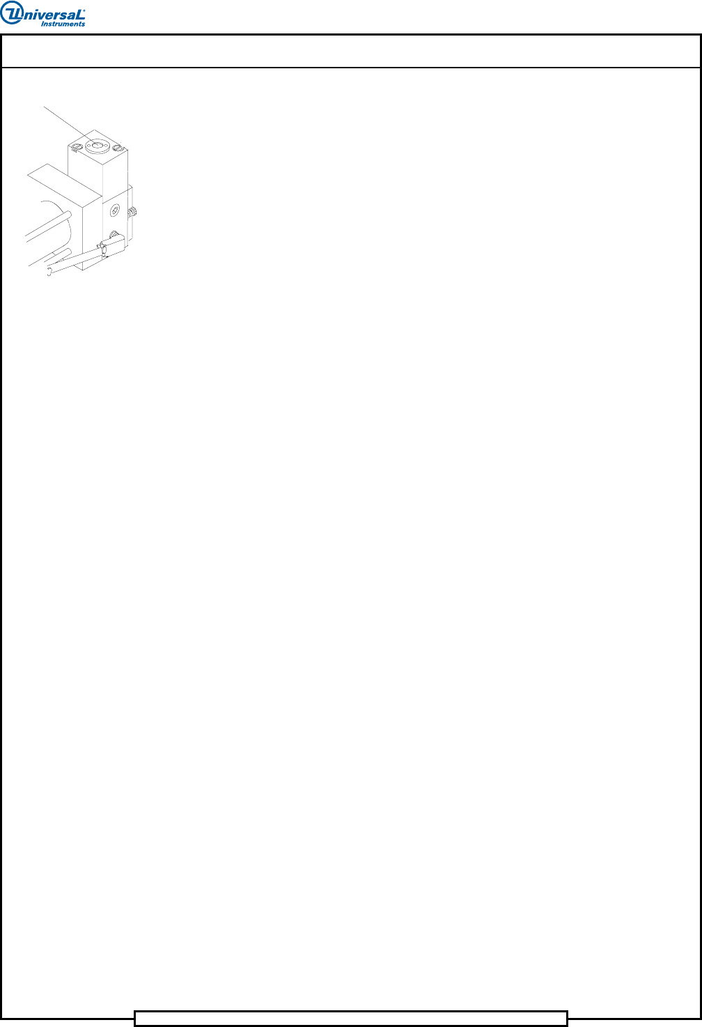
Each pneumatic valve contains a plunger that allows the user to manually
actuate the valve. Actuating the valve in this manner assists in determining
whether the pneumatics or electrical controls are the cause of a specific
problem. If a valve does not operate, and pushing the plunger causes the
valve to operate, an electrical problem exists. If the valve fails to operate
when the plunger is pushed, a pneumatic or mechanical problem exists.
Troubleshooting Tables
The troubleshooting tables are another technique that gives the technician a
place to start. Some of the tables are symptom driven while other tables or
items within tables require that the technician first isolate the functional
problem to an assembly. After isolating the functional problem, use the
appropriate machine drawings to further troubleshoot the machine to a
specific component malfunction and then repair. For repairs requiring
adjustments or setup procedures, refer to the Maintenance Manual.
Machine Sequence of Events
The insertion machine dispenses leaded components from taped input
packages then inserts the components to a programmed location and
orientation in a printed circuit board.
The general sequence of events for the insertion cycle of the insertion
machine is as follows.
1. The feeders, located on the sequencer modules, remove the axial
leaded components from the input packages.
2. The feeders place the components in a programmed sequence on the
sequencer chain. The refire function will continue to fire the head a
programmed number of times to ensure a component is in place when
gaps in the presequenced tapes are encountered.
3. The sequencer chain transports the components to the insertion chain
clips.
4. The insertion chain clips transport the components to the missing part
sensor, centering assembly, and then to the insertion head tooling.
5. As the components are being transported to the insertion tooling, a
board is positioned to the programmed coordinates for component
insertion.
6. Component presence is checked at the missing part sensor and correct
component value is verified at the optional verifier assembly. If either
operation fails to meet programmed specifications, a repair function
allows the operator to correct the condition.

Page 4
52489101 Rev. B IM Troubleshooting
This document supports Radial 88, VCD Seq 88, and Jumper Wire 88 machines.
7. While the centering assembly centers a component two positions
before the insertion position, the cut and clinch assembly raises to the
bottom of the board.
8. The insertion tooling cuts the components from the insertion chain
clips, forms the component leads, and then inserts the components at
the programmed position in the board.
9. The cut and clinch assembly senses component lead presence, cuts the
component leads, and then forms the component leads under the board
creating a mechanical bond to the board.
10. The insertion head tooling and cut and clinch assembly retract
completing the component insertion sequence.
11. The process continues until the pattern program is complete and all
required components are in place.
VME System
The following information on the VME is primarily symptom driven. It is
already assumed that if the machine fails to operate the most logical causes
have been checked. For example, all machine components are plugged in,
circuit breakers are on, interlock is not broken (doors closed) and machine is
not in a limit condition.
To troubleshoot the VME, it is recommended that the technician have an
understanding of the layout and the available reference documentation;
electrical drawings, IM UPS and IM Diagnostics.
The VME hardware consists of 7 major elements:
• Power Supply
• VME bus Backplane
• Embedded PC (separate from the VME Bus)
• Real-time Controller
• Motion Controller or Controllers
• Mini MIT Interface (VCD/Sequencer only)
Page 5
IM Troubleshooting 52489101 Rev. B
This document supports Radial 88, VCD Seq 88, and Jumper Wire 88 machines.
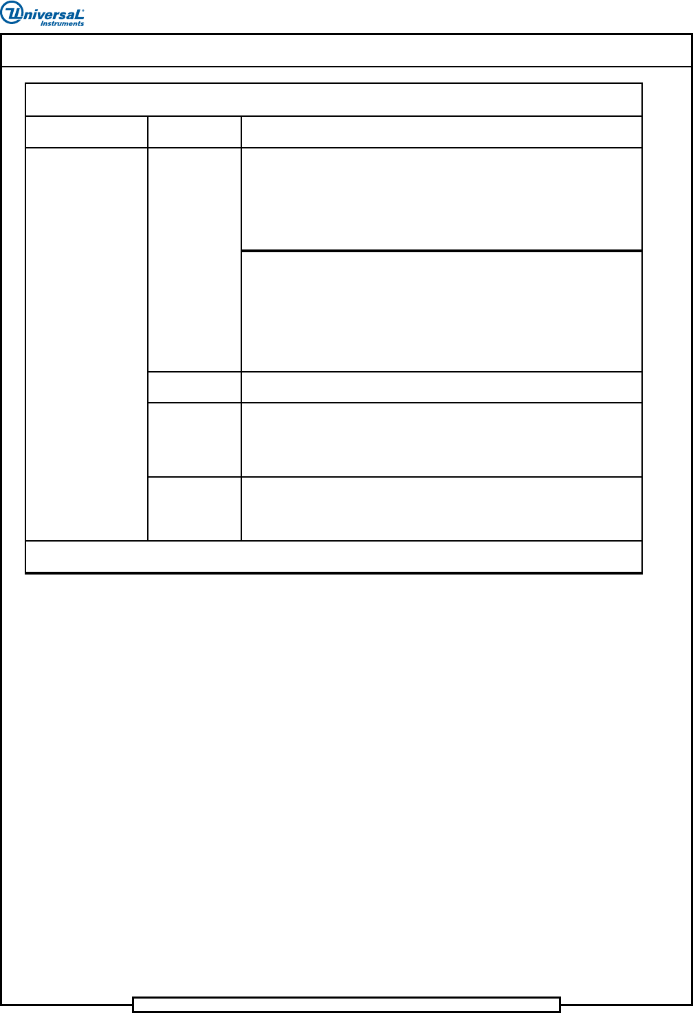
Problem Check
Power Supply:
ATX
LED Display
The VME chassis power supply accepts 120 VAC and output.
Voltages at the back plane are as follows:
+5 VDC (4.90 to 5.20)
+12 VDC (11.70 to 12.5)
-12 VDC (-11.7 to -12.5)
Power Supply:
VME Chassis
Machine does not run
Con tinued on next pa ge…
AC Voltage should be checked at the AC chassis, then at the VME power supply
and ATX power supply input. If not present, check VME input fuse.
AC Voltage
(Qty of 2)
Troubleshooting Table - VME System
Comments/Corrective Action
DC voltages from the power supply in the VME are adjustable through the cover
on the power supply.
Voltages at the back plane are as follows:
+5 VDC (5.00 to 5.10)
+12 VDC (12.00 to 12.20)
-12 VDC (-12.00 to -12.20)
Normal LED display is:
"Run" LED on PC-2 (Real Time Controller) illuminated at all times.
"BM" LED illuminated when PC-2 is communicating with the bus.
"Run" LED on PC-1 (embedded PC) blinking when computer is in use.
See the VME Chassis Electrical Diagram.
(Fuse is located inside the power entry module, accessed from rear of VME
chassis.) Input range for VME is 90 to 132 VAC.