00198624-01 RI XFVS camera position de en.pdf - 第18页
Retrofit the XFVS c amera position Ausgabe 08/2017 Edition 18 2.3 Disassembly 2.3.1 Removing the camera tower Fig. 2: Feet at the back of the XFVS ► Remove the left and ri ght foot at th e back of the station. Fig. 3: Sc…
Retrofit the XFVS camera position Ausgabe 08/2017 Edition
17
2 Refit the camera position
NOTE
New calibration tool
For the calibration of the modified XFVS a new calibration tool is required.
► 03146176-02 Calibration tool XFTS complete.
2.1 Retrofit XFVS camera position 12mm [03168448-01]
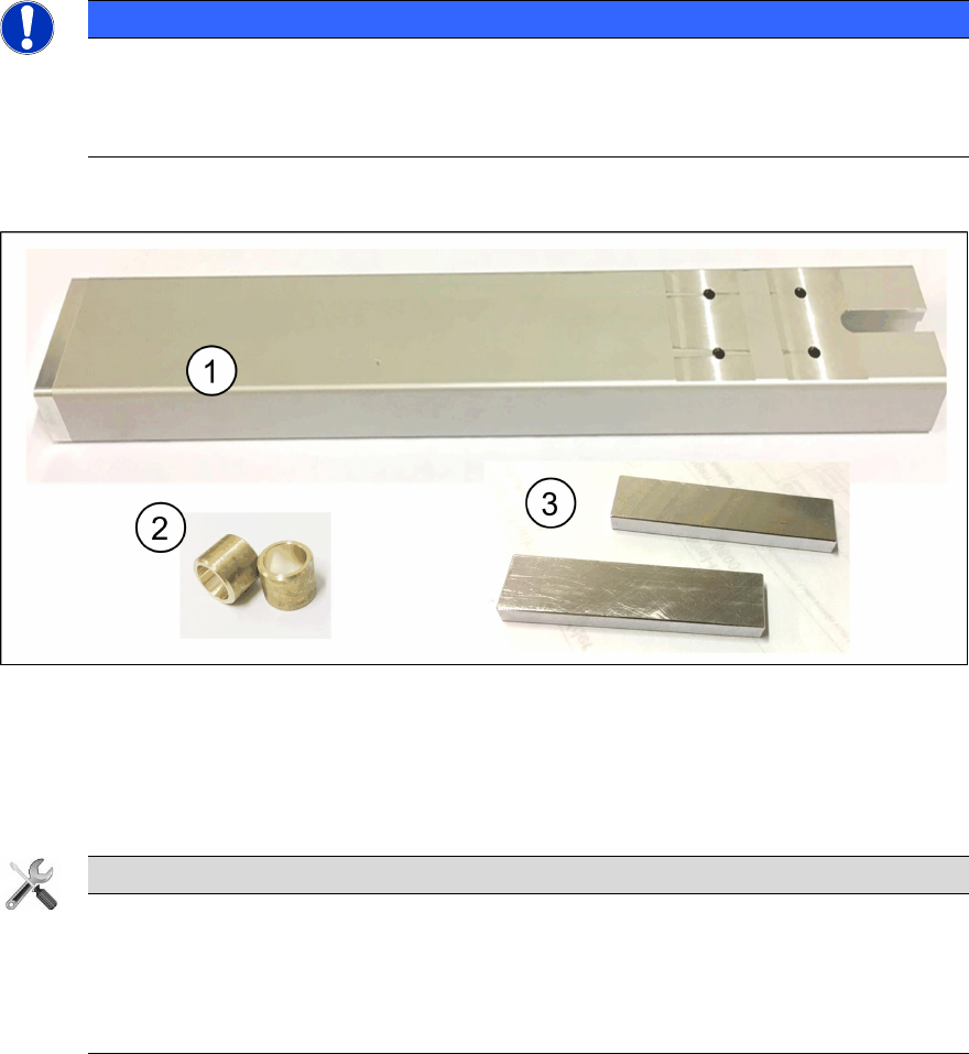
Fig. 1: 03168448-01 Refit kit XFVS 12mm offset camera column
4. 1x Camera tower with mounted adapter
5. 2x Sleeves
6. 2x Adjustment aid
Tools
Required tools for the retrofit!
● Allen key 2,5 mm, 5 mm and 6 mm
● Open-end or ring spanner size 10
● Side cutter
2.2 Preparing the XFVS for the retrofit
Before starting to disassemble the camera tower the following steps need to be performed.
► Switch off the X-Feeder Verification System at the main switch.
► Remove any device from the X-Feeder Verification System.
► Disconnect all cables at the back of the X-Feeder Verification System.
● Power Supply
● USB vision connection
● USB-CAN-Bus adapter
Retrofit the XFVS camera position Ausgabe 08/2017 Edition
18
2.3 Disassembly
2.3.1 Removing the camera tower
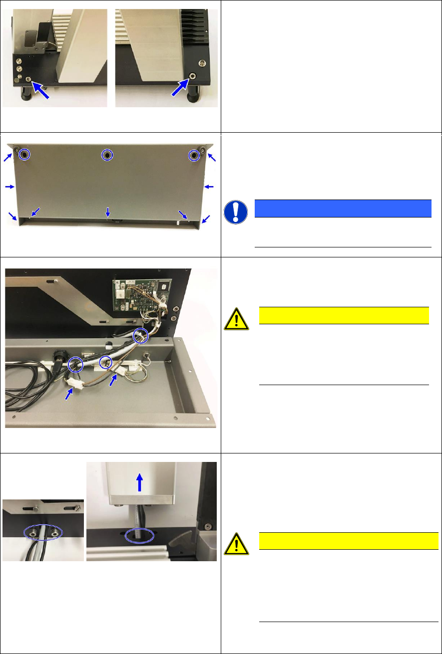
Fig. 2: Feet at the back of the XFVS
► Remove the left and right foot at the back of
the station.
Fig. 3: Screws at the base plate
► Place the XFVS on the back, on a clean and
even work surface.
► Remove all screws from the housing.
NOTICE
At newer XFVS the outer screws at
the top were omitted.
Fig. 4: XFVS connection - base plate to housing
► Remove the housing from the baseplate and
lay it in front of it.
CAUTION
Connecting cable
The housing is connected by cable
to the base plate. Be careful not to
damage any cable!
► Remove the 3 cable ties and disconnect the
2 cables from the base plate.
► Place the housing at a protected place to the
side.
Fig. 5: Camera tower interface
► Remove the 2 screws on the camera tower
and detach it from the base plate.
► Carefully thread the camera cable through
the opening.
CAUTION
Firm seating and small opening
The camera tower sits firmly on the
base plate and the opening for the
cables is at some XFVS very small. Be
careful not to damage any cable!
► Place the base plate on a protected surface
to the side.
Retrofit the XFVS camera position Ausgabe 08/2017 Edition
19
2.3.2 Removing the camera
CAUTION
Risk of damage
The camera is a very sensitive device. Carry out all subsequent work very carefully to
prevent any damage to the system!
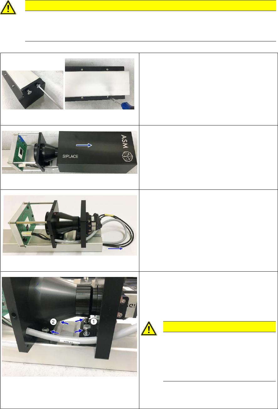
Fig. 6: Screws at the camera cover and housing
► Place the camera tower with the camera
down on a clean and even work surface.
► Remove the 2 screws from the camera cover
and remove it.
► Remove the 4 screws from the housing.
Fig. 7: Removing the camera housing
► Turn the camera tower around the
longitudinal axis and place it on the camera
support.
► Remove the camera housing by sliding it
upwards.
Fig. 8: Taking out the camera cables
► Carefully pull the camera cables out of the
camera support.
Fig. 9: Screws fixing the camera to the support
► Remove the 2 screws (1) at the upper
camera carrier.
► Loosen the 2 screws at the lower camera
carrier until just before the lens.
CAUTION
Risk of damaging the camera!
If the screws are turned against the
lens there is a risk of damaging it.
Be careful not to twist the camera
when removing it!
► Remove the 2 screws alternately while
simultaneously lifting the lower camera
carrier until you can remove the camera.