00198624-01 RI XFVS camera position de en.pdf - 第21页
Retrofit the XFVS c amera position Ausgabe 08/2017 Edition 21 Fig. 14 : Screws fixing the camer a to the support ► Clean the contact s urface o f the cam era. ► Position the cam era with the scr ews at the lower camera c…
Retrofit the XFVS camera position Ausgabe 08/2017 Edition
20
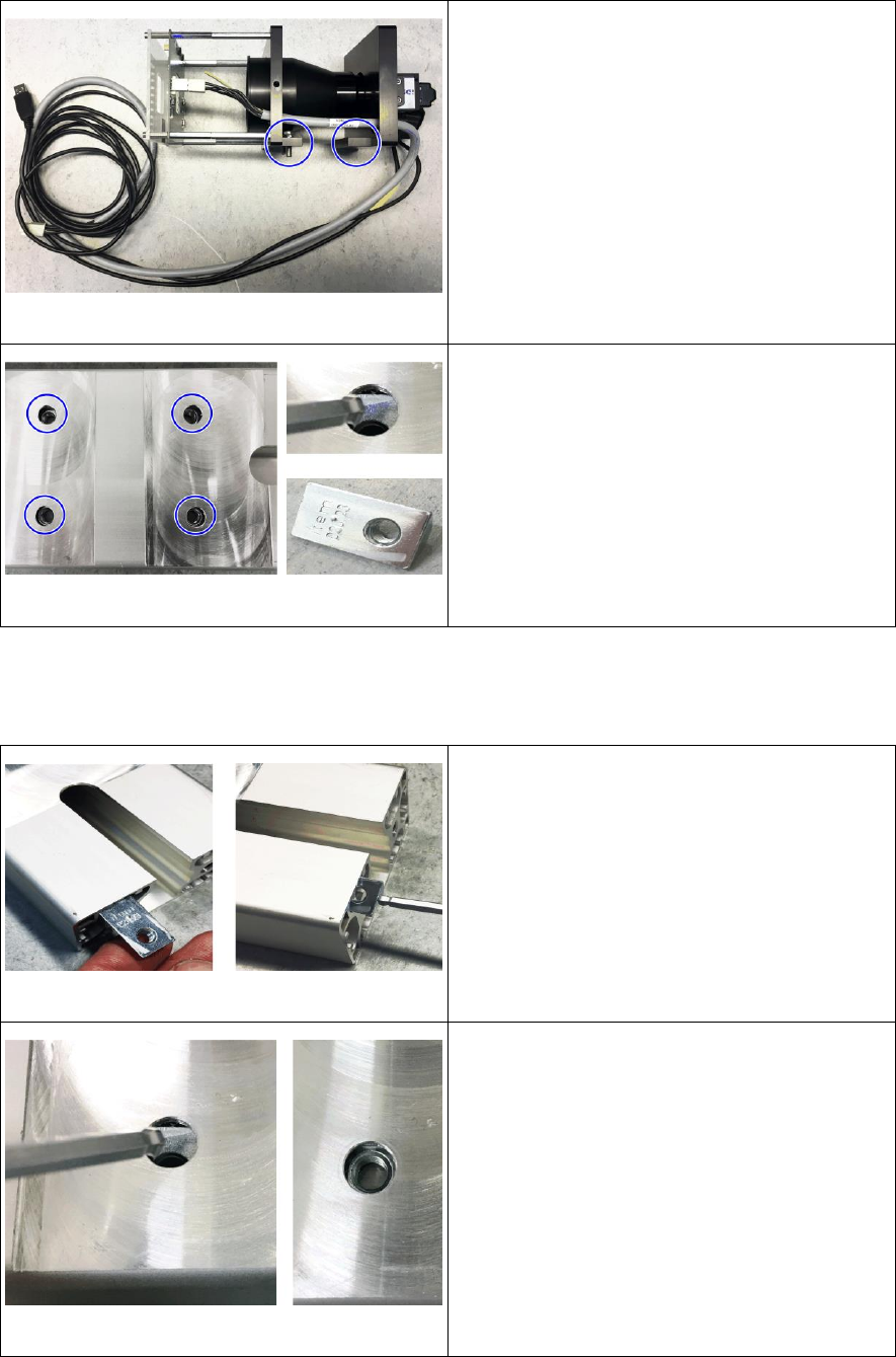
Fig. 10: Complete camera removed
► Place the camera on the side at a protected
surface without twisting it.
Fig. 11: Removing the hammer nuts
► Remove the 4 hammer nuts from the camera
support.
► To do so tilt all 4 nuts to the side let them
slide out of the camera support.
2.4 Assembly
2.4.1 Mounting the camera
Fig. 12: Inserting the hammer nuts
► Insert all 4 hammer nuts into the camera
support.
► To do so insert the nut into the support with
the long side ahead.
► Push the nut until the thread can be seen
under the hole.
Fig. 13: Positioning the hammer nuts
► Tilt the hammer nut there and align the
thread with the opening.
► Proceed accordingly for the other nuts.
Retrofit the XFVS camera position Ausgabe 08/2017 Edition
21
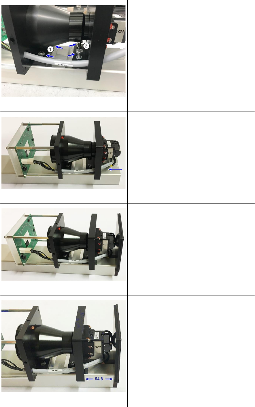
Fig. 14: Screws fixing the camera to the support
► Clean the contact surface of the camera.
► Position the camera with the screws at the
lower camera carrier (1) over the threads. Be
careful not to twist the camera when
mounting it
► Alternately tighten the 2 screws slightly.
Make sure that the screws do not press
against the camera lens at any time.
► Insert the 2 screws at the upper camera
carrier (2) und tighten them slightly.
Fig. 15: Inserting camera cable
► Carefully push the camera cables through
the camera support and the adapter mounted
to it until they sit neatly in the gap.
Fig. 16: Mounting the camera cover
► Mount the camera cover with the 2 screws.
Fig. 17: Fixing the camera
► Loosen the screws at the camera so that you
can move the camera.
► Insert die adjustment aids at both sides
between camera carrier and cover.
► Hand-tighten the 4 screws in this position.
► The distance between upper camera carrier
and cover should now be 55 mm.
► Repeat the adjustment if necessary.
Retrofit the XFVS camera position Ausgabe 08/2017 Edition
22
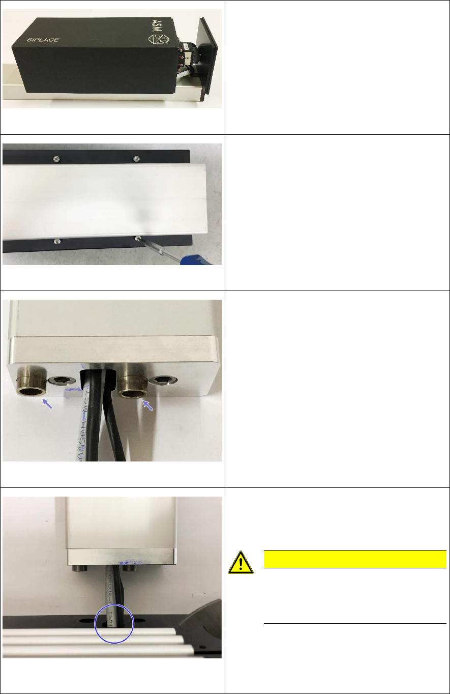
Fig. 18: Mounting the camera housing
► Slide the camera housing onto the camera.
Fig. 19: Tightening the screws at the camera housing
► Turn the camera tower carefully around the
longitudinal axis and place it on the camera
housing.
► Align the camera housing flush with the
camera cover and hand-tighten all 4 screws
in this position.
Fig. 20: Inserting the sleeves
► Turn the camera tower around the
longitudinal axis and place it on the camera
support.
► Insert the sleeves at the adapter mounted to
the camera support.
Fig. 21: Threading the camera cable through the base
plate
► Place the base plate in front of the adapter
and thread the camera cables through the
opening in the plate.
CAUTION
Be careful not to damage the
camera cables or the connectors
when threading them through the
opening!