00198624-01 RI XFVS camera position de en.pdf - 第20页
Retrofit the XFVS c amera position Ausgabe 08/2017 Edition 20 Fig. 10 : Complete cam era removed ► Place the cam era on the side at a pro tected surface without twis ting it. Fig. 11 : Removing the ha mmer nuts ► Remove …
Retrofit the XFVS camera position Ausgabe 08/2017 Edition
19
2.3.2 Removing the camera
CAUTION
Risk of damage
The camera is a very sensitive device. Carry out all subsequent work very carefully to
prevent any damage to the system!
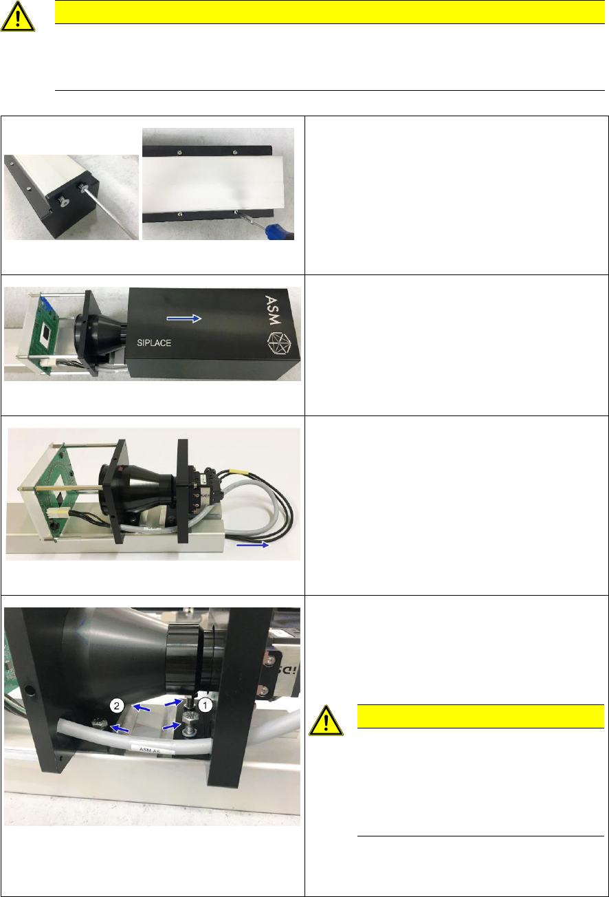
Fig. 6: Screws at the camera cover and housing
► Place the camera tower with the camera
down on a clean and even work surface.
► Remove the 2 screws from the camera cover
and remove it.
► Remove the 4 screws from the housing.
Fig. 7: Removing the camera housing
► Turn the camera tower around the
longitudinal axis and place it on the camera
support.
► Remove the camera housing by sliding it
upwards.
Fig. 8: Taking out the camera cables
► Carefully pull the camera cables out of the
camera support.
Fig. 9: Screws fixing the camera to the support
► Remove the 2 screws (1) at the upper
camera carrier.
► Loosen the 2 screws at the lower camera
carrier until just before the lens.
CAUTION
Risk of damaging the camera!
If the screws are turned against the
lens there is a risk of damaging it.
Be careful not to twist the camera
when removing it!
► Remove the 2 screws alternately while
simultaneously lifting the lower camera
carrier until you can remove the camera.
Retrofit the XFVS camera position Ausgabe 08/2017 Edition
20
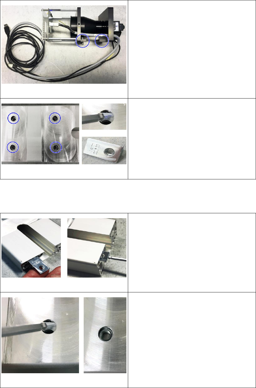
Fig. 10: Complete camera removed
► Place the camera on the side at a protected
surface without twisting it.
Fig. 11: Removing the hammer nuts
► Remove the 4 hammer nuts from the camera
support.
► To do so tilt all 4 nuts to the side let them
slide out of the camera support.
2.4 Assembly
2.4.1 Mounting the camera
Fig. 12: Inserting the hammer nuts
► Insert all 4 hammer nuts into the camera
support.
► To do so insert the nut into the support with
the long side ahead.
► Push the nut until the thread can be seen
under the hole.
Fig. 13: Positioning the hammer nuts
► Tilt the hammer nut there and align the
thread with the opening.
► Proceed accordingly for the other nuts.
Retrofit the XFVS camera position Ausgabe 08/2017 Edition
21
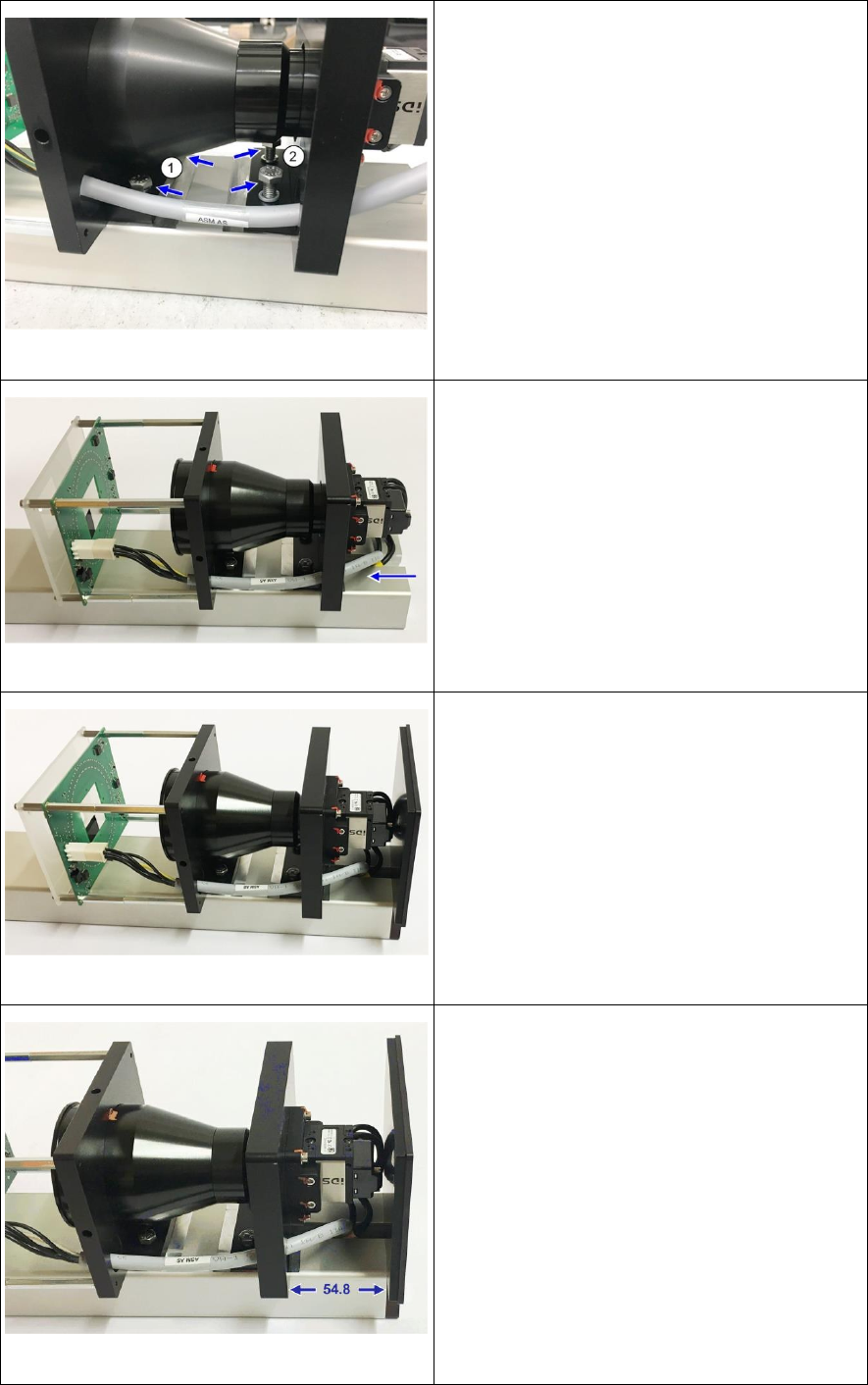
Fig. 14: Screws fixing the camera to the support
► Clean the contact surface of the camera.
► Position the camera with the screws at the
lower camera carrier (1) over the threads. Be
careful not to twist the camera when
mounting it
► Alternately tighten the 2 screws slightly.
Make sure that the screws do not press
against the camera lens at any time.
► Insert the 2 screws at the upper camera
carrier (2) und tighten them slightly.
Fig. 15: Inserting camera cable
► Carefully push the camera cables through
the camera support and the adapter mounted
to it until they sit neatly in the gap.
Fig. 16: Mounting the camera cover
► Mount the camera cover with the 2 screws.
Fig. 17: Fixing the camera
► Loosen the screws at the camera so that you
can move the camera.
► Insert die adjustment aids at both sides
between camera carrier and cover.
► Hand-tighten the 4 screws in this position.
► The distance between upper camera carrier
and cover should now be 55 mm.
► Repeat the adjustment if necessary.