00198624-01 RI XFVS camera position de en.pdf - 第23页
Retrofit the XFVS c amera position Ausgabe 08/2017 Edition 23 Fig. 22 : Mounting t he came ra tower to the base plate CAUTION Firm seating and sm all opening The sleeves m ust be pulled into th e corresponding openi ngs …
Retrofit the XFVS camera position Ausgabe 08/2017 Edition
22
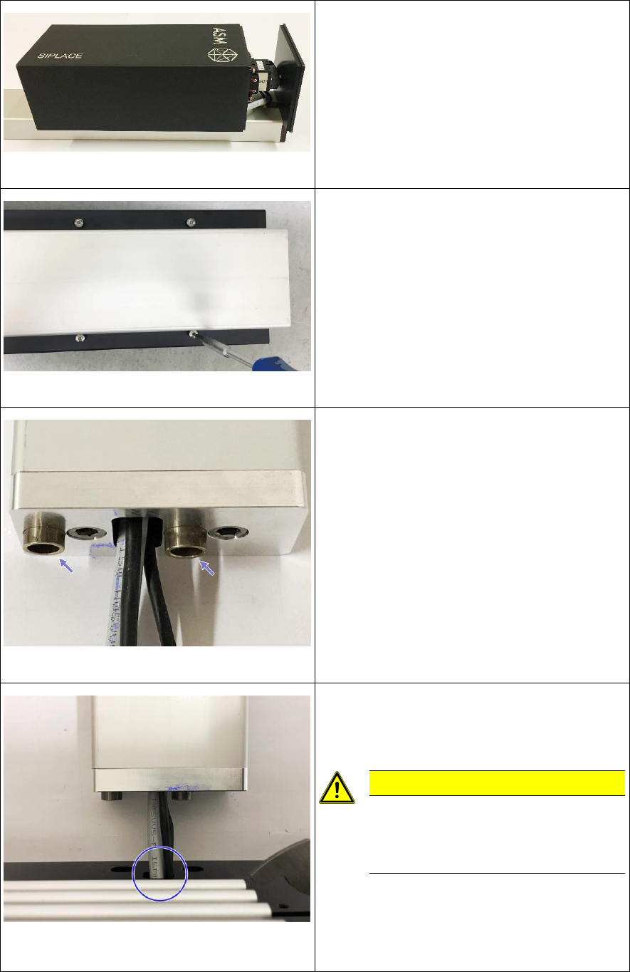
Fig. 18: Mounting the camera housing
► Slide the camera housing onto the camera.
Fig. 19: Tightening the screws at the camera housing
► Turn the camera tower carefully around the
longitudinal axis and place it on the camera
housing.
► Align the camera housing flush with the
camera cover and hand-tighten all 4 screws
in this position.
Fig. 20: Inserting the sleeves
► Turn the camera tower around the
longitudinal axis and place it on the camera
support.
► Insert the sleeves at the adapter mounted to
the camera support.
Fig. 21: Threading the camera cable through the base
plate
► Place the base plate in front of the adapter
and thread the camera cables through the
opening in the plate.
CAUTION
Be careful not to damage the
camera cables or the connectors
when threading them through the
opening!
Retrofit the XFVS camera position Ausgabe 08/2017 Edition
23
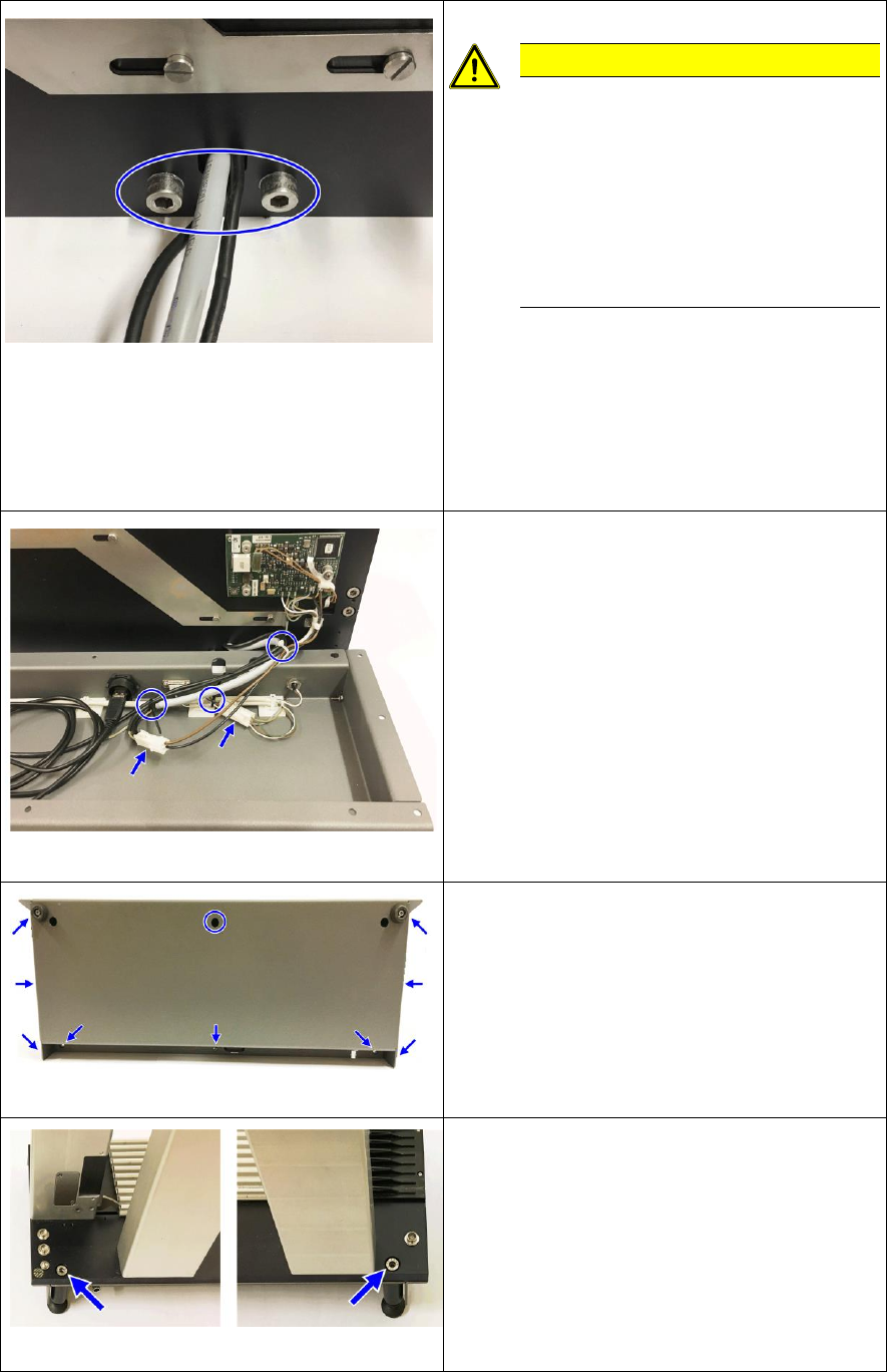
Fig. 22: Mounting the camera tower to the base plate
CAUTION
Firm seating and small opening
The sleeves must be pulled into the
corresponding openings when
tightening in order to ensure a firm
position of the camera tower on the
base plate.
Be careful not to damage a camera
cable while doing so.
► Position the sleeves in the adapter over the
openings in the base plate.
► Clean the opposite surfaces of the adapter
and the base plate.
► Insert the screws and fix them hand-tight
alternately until the adapter sits firmly on the
base plate.
Fig. 23: Connect the base plate with the housing
► Put the housing on front of the base plate.
► Connect the 2 cables and fix the cables at
the 3 marked positions with cable ties.
Fig. 24: Screws fixing the base plate to the housing
► Align the housing with the base plate and
hand-tighten all screws in this position
starting with the screw in the middle at the
top.
Fig. 25: Feet at the back of the XFVS
► Replace the 2 rear feet of the system and
hand-tighten them.
► The conversion is now complete
Retrofit the XFVS camera position Ausgabe 08/2017 Edition
24