JAKA Zu 7电控柜V2.1-硬件手册(英文版).pdf - 第18页
16 3.1.1 Rob ot Dimensio ns Fig3-2 Fig3-3 3.1.2 Rob ot Working Ran ge The photo and dim ensions of J AKA Zu 7 robot and electrical cabinet are shown in Fig 3-2 and F ig3-3. Make sur e to take into account the working r a…
15
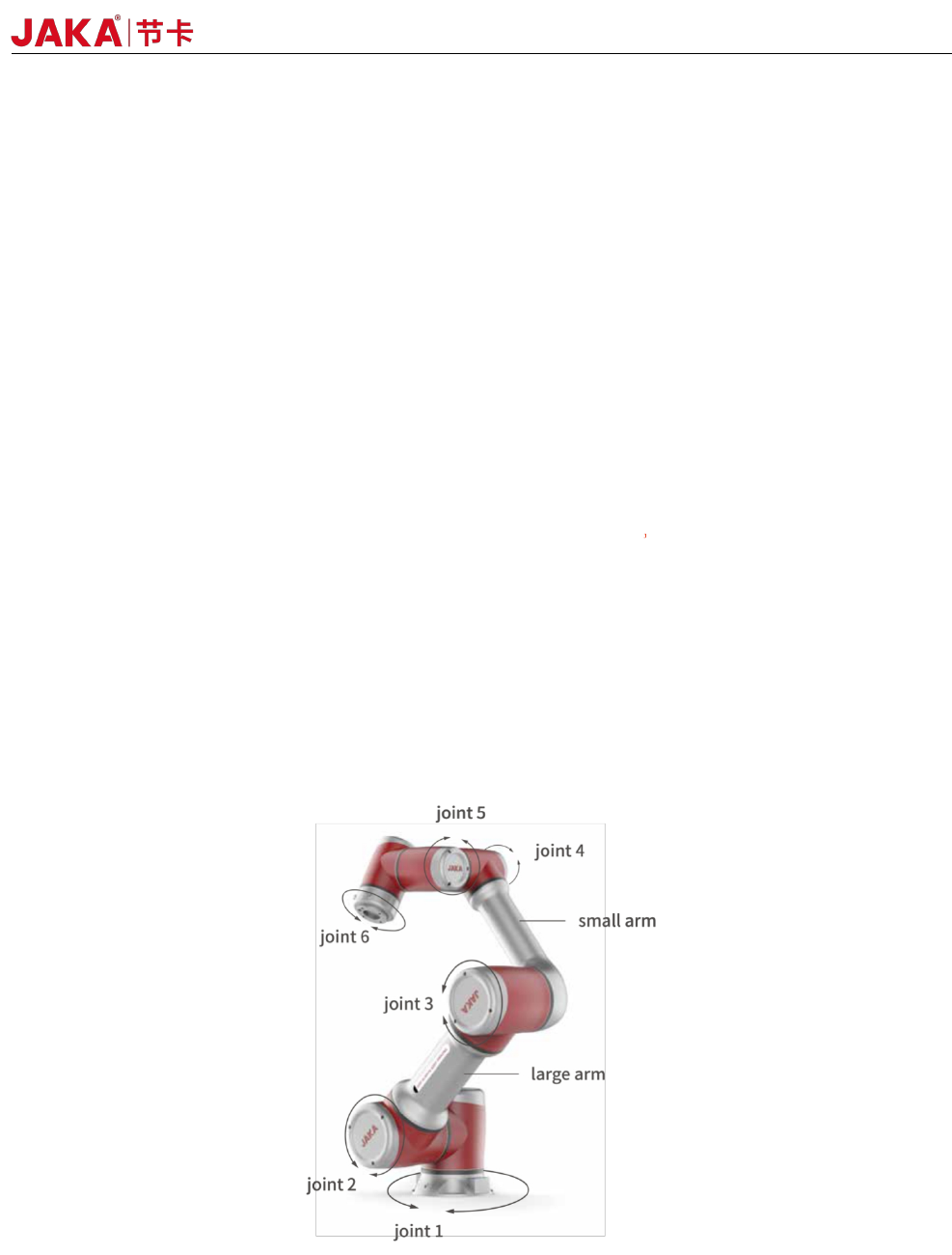
Fig 3-1
3.1 Robot Working Range
JAKA Zu 7 v2.5
The robot consists mainly of six joints and two aluminum tube arms (as shown in Fig3-1). The base is used
to install the robot, and the tool end is used to mount the tool. The tool can perform translational and rotational
movements in the robot's working range. The following sections describe the basics to be aware of the
installation of various components in the robot system.
3 Mechanical Specification
16
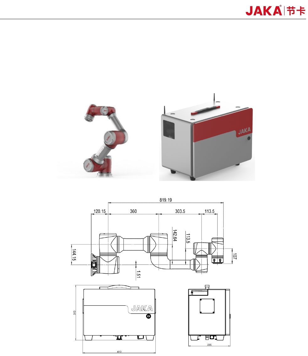
3.1.1 Robot Dimensions
Fig3-2
Fig3-3
3.1.2 Robot Working Range
The photo and dimensions of JAKA Zu 7 robot and electrical cabinet are shown in Fig 3-2 and Fig3-3.
Make sure to take into account the working range of the robot during installation to avoid injury to
people or damage to the equipment.
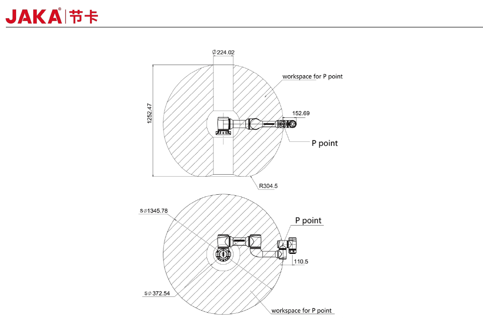
The working range of JAKA Zu 7 is shown in Fig 3-4. When choosing the robot installation
position, the cylinder space directly above and below the robot must be considered. Moving the tool close to
the cylindrical volume should be avoided if possible, because it causes the joints to move fast even though the
tool is moving slowly, causing the robot to work inefficiently and making it difficult to conduct a risk assessment.
JAKA Zu 7 V2.5 a
17
Fig3-4
JAKA Zu 7 v2.5