JAKA Zu 7电控柜V2.1-硬件手册(英文版).pdf - 第30页
28 . Figure 4-10 Figure 4-10 shows the input wiring diagr am of the PNP interf ace. The V + pin is c onnected to V +, the OUT pin is connec ted to DIx , and the 0V pin is c onnected to V- . W hen the signa l is triggered…
27
4.3.2 Digital Input (DI)
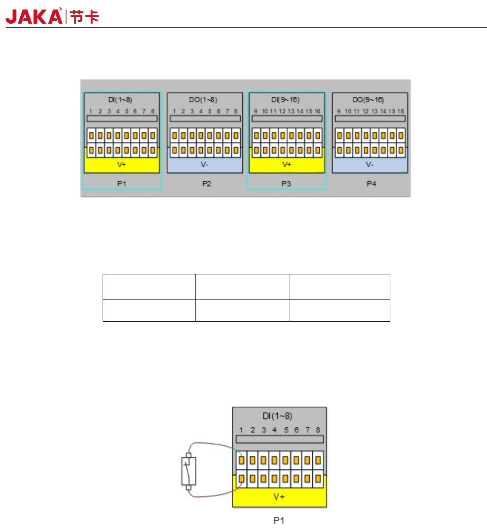
Fig 4-8
The electrical cabinet is equipped with 16 digital PNP type input(Active high) (DI1 ~ DI16) to support
isolated signal input. The level signal satisfies the IEC61131-2 (Type1/2/3) standard and is used to detect the
input signal level status.
V+
Voltage
Low range High range
24V
0~11V 15~24V
The V+ interface supports external 10~35V power input. The factory default uses internal 24V power
supply. The high level range is 15~24V, and the low level range is 0~11V.
Users can also connect DIx to V+ directly.
Different types of input signals have different connections. The specific connection methods are as follows:
a) Dry contact signal as input
Figure 4-9
During dry contact input, one of the wires is connected to V + and the other wire is connected to DIx. When
the circuit is on (as shown in the figure, the switch or relay is closed), the corresponding LED turns on. You can
also see the DIx status on the APP interface
b) PNP type signal as input
JAKA Zu 7 v2.5
28
.
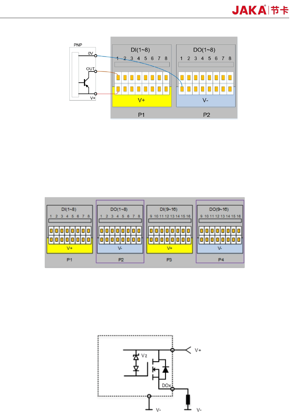
Figure 4-10
Figure 4-10 shows the input wiring diagram of the PNP interface. The V + pin is connected to V +, the OUT
pin is connected to DIx, and the 0V pin is connected to V-. When the signal is triggered, the LED on the panel
turns on, and the DIx status on the APP interface is changed.
4.3.3 Digital Output(DO)
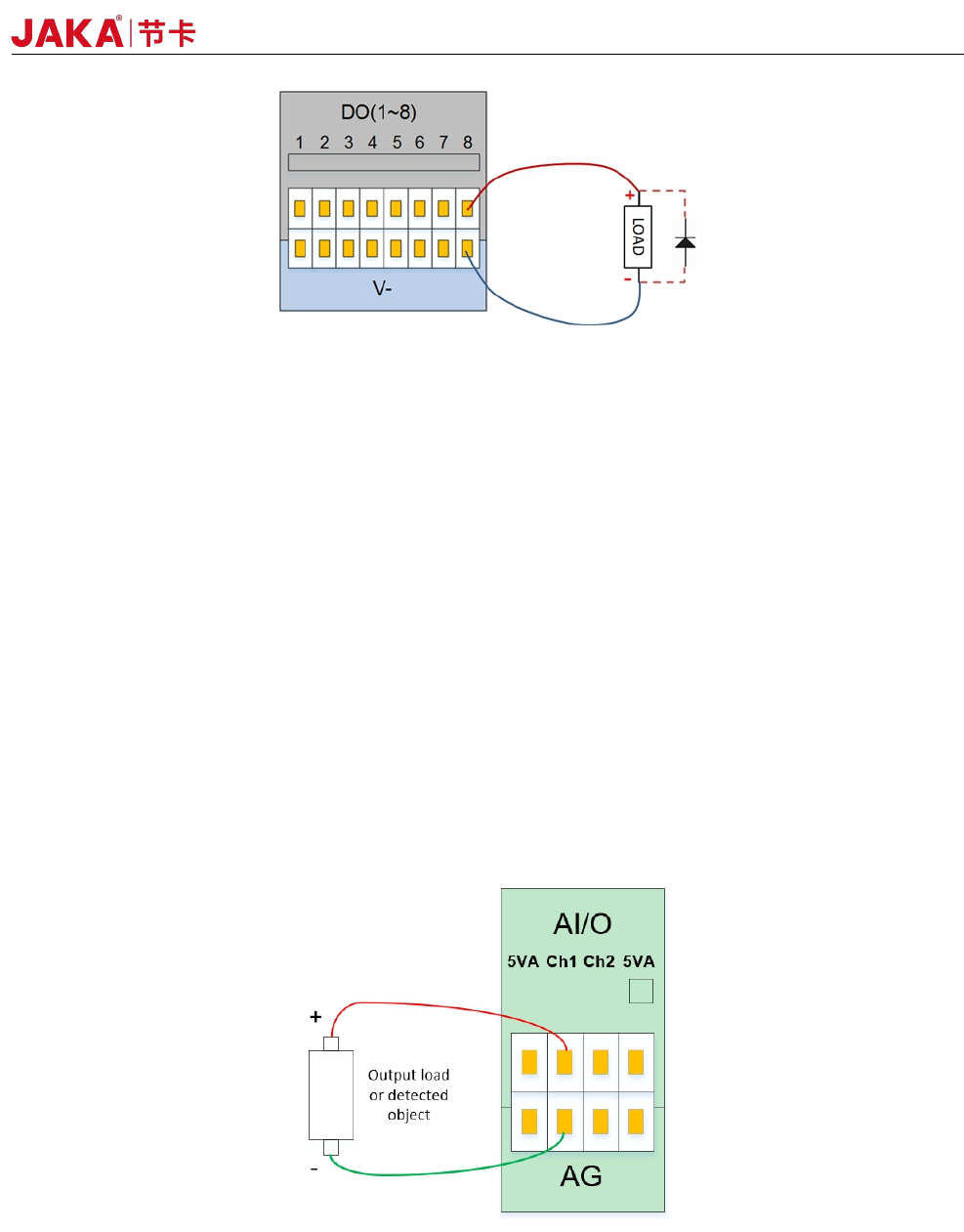
Figure 4-11
The electric control cabinet has 16 channels PNP type output interface (DO1 ~ DO16) to support isolated
signal output.
The digital output uses a high-side output with a single continuous maximum current of 1A. However,
when V+ defaults to internal 24V power supply, the 24V power supply is limited to 1.5A. The typical internal
circuit diagram is as follows:
Figure 4-12
The typical block diagram is as follows:
JAKA Zu 7 V2.5
29
Fig 4-13
The digital output module can be controlled by the DO function of the APP. The user needs to
control the load power when using it. The single channel should not exceed 1A current, and the DO
output current should not exceed the maximum output current of the power supply.
* Note: It is strongly recommended to use protection DIODES for the inductive loads (such as relays,
electromagnets, DC motors, etc.).
4.3.4 Analog Input&Output(AI&AO)
The electrical cabinet has 2 analog input and output interfaces (Ch1, Ch2), the input mode can be
configured, and the AI mode is as follows:
1) Current signal input: 4 to 20 mA.
2) Voltage signal input: 0~5V, 0~10V, -10V~+10V.
3) Current signal output: 0~20mA
4) Voltage signal output: 0~5V, 0~10V, -10V~+10V.
The wiring method for analog input and output is shown in Figure 4-13.
Figure 4-14
The JAKA CAB V2 AI/O interface can be configured to work in different modes (factory default is
0~10V analog input). The user can set the AI/O working mode through the APP.
For high accuracy, the following instructions are recommended:
• Use the AG terminal closest to the AI/O.
JAKA Zu 7 v2.5