JAKA Zu 7电控柜V2.1-硬件手册(英文版).pdf - 第26页
24 9 SI2 The protecti on stop f unction input 2, the fac tory default is V+ 10 SI1 The protecti on stop f unction input 2, the fac tory default is V+ 1 1 EI2 Emergenc y stop func tion input 2, the factory default is V+ 1…
23
4 DO12
12th digital output, PNP Type, ≤1A continuous
current output capability
5 DO13
13th digital output, PNP Type, ≤1A continuous
current output capability
6 DO14
14th digital output, PNP Type, ≤1A continuous
current output capability
7 DO15
15th digital output, PNP Type, ≤1A continuous
current output capability
8 DO16
16th digital output, PNP Type, ≤1A continuous
current output capability
9~16 V-
Isolated power input negative, default shorting is
connected to internal GND
P5 AI/O
1、4
5VA Analog power supply 5V output, 100mA (max)
2 Ch1 Analog input/output channel 1
3 Ch2 Analog input/output channel 1
5~8 AG Analog ground
P6 HSI
1、8 5VD Digital power supply 5V output, 100mA (max)
2、3
1P Differential signal 1 input positive / encoder A +
14、15 1N Differential signal 1 input negative / encoder A-
4、5 2P Differential signal 2 input positive / encoder B+
12、13
2N Differential signal 2 input negative / encoder B-
6、7 3P Differential signal 3 input positive / encoder Z +
10、11
3N Differential signal 3 input negative / encoder Z-
9、16 DG Digital ground
P7 -
1、2
VSB
Internal power supply 5V, 100mA (max), can be
used for remote power on/off
3 0V Internal GND (internal 24V, 12V reference ground)
4、5 485B RS485 B
6、7 485A RS485 A
8 V-
Isolated power input negative, default shorting is
connected to internal GND
9 OFF
Remote shutdown signal input, high level (5~24V) is
valid
10 ON
Remote power-on signal input, high level (5~24V) is
valid
P8 -
1~4、8
V+
Isolated power input is positive, factory default is
connected to internal 24V
5 24V
The internal 24V output is positive and supports a
maximum of 1.5A current output
6 0V The internal 24V power supply output is negative
7 V-
The isolated power input is negative, and the factory
default is connected to the internal GND
JAKA Zu 7 v2.5
24
9 SI2
The protection stop function input 2, the factory
default is V+
10 SI1
The protection stop function input 2, the factory
default is V+
11 EI2
Emergency stop function input 2, the factory default
is V+
12 EI1
Emergency stop function input 1, the factory default
is V+.
P9 - - USB USB3.0
P10 - - Ethernet1Gigabit Ethernet interface
4.3.1 All digital I/O common specifications
This section describes the electrical specifications for 24V digital I/O using an electrical cabinet. Can be
divided into: V + power selection, security I / O configuration.
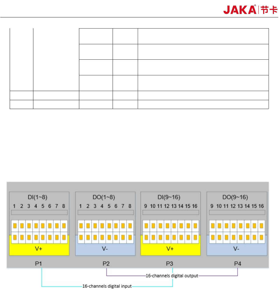
The electrical cabinet supports 16 digital inputs and 16 digital outputs, as shown in Figure 4-2.
Figure 4-2
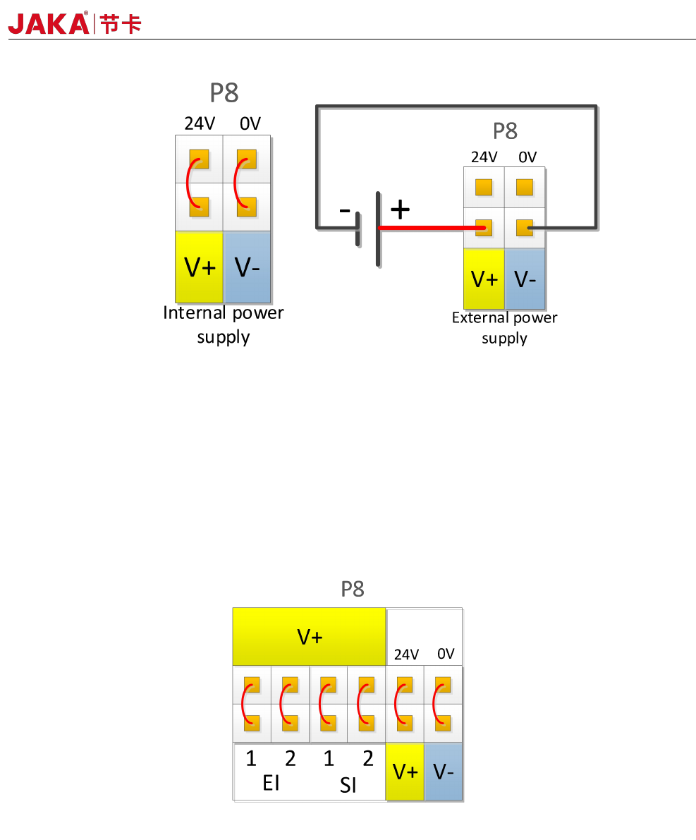
The digital I/O can be powered by a 24V power supply provided inside the control cabinet and supports up
to 1.5A output (overload will turn off the output). When the user needs more power output, the V+ power supply
can be powered by an external "24V power supply". 24V is the internal power supply and 0V is the internal
ground. V+ is the positive pole of the digital I/O interface, and V- is the negative pole of the digital I/O interface.
The factory default configuration is internal power, see Figure 4-3 below.
JAKA Zu 7 V2.5
25
Figure 4-3
The electrical cabinet has a dedicated safety I/O interface, and the user can configure two functions:
emergency stop and protection stop. The function description is detailed in section 4.3.7. Here are some
examples of how safe I / O interface.
1. Factory configuration.
Users can use the robot without any additional safety equipment. If EI1~2 and SI1~2 are both connected to
V+, V+ is connected to 24V, and V- is connected to 0V, it indicates that 24V power is provided inside the
electrical cabinet. As shown in Figure 4-4.
Figure 4-4
2、Connect the emergency stop switch.
The user needs to use one or more additional emergency stop or guard stop switches, please refer to Figure
4-5 and Figure 4-6 for wiring. Figure 4-5 and Figure 4-6 show how to use one or more emergency stop
switches. The example uses an internal 24V power supply and the user can also use an external 24V power
supply.
JAKA Zu 7 v2.5