JAKA Zu 7电控柜V2.1-硬件手册(英文版).pdf - 第36页
34 Figure 4-20 Figure 4-20 shows the block diagram of the NPN input devic e connection: the V + pin is conne cted to + 24V (red wire), the 0V pin is conne cted to the negative pol e (gray wire) , and the OUT pin is conne…
33
n Internal connect4.7k resistor.
4 DO1 O
yello
w
Digital output 1. NPN type. Open Drain output. Current
≤0.5A per channel.
5 DO2 O
Pink Digital output 2. NPN type. Open Drain output. Current
≤0.5A per channel.
6 AIN_P I
brow
n
Analog input.Supports -10V~+10V voltage input. Decouple
with the AIN_N pin.
7 AIN_N I
white Analog input:Negative. Decouple with the AIN_P pin.
8 GND -
gray GND. 24V Power Ground.
1. TIO analog input interface
Analog input AI1 supports -10V~+10V high precision voltage range input.
2. TIO digital input interface
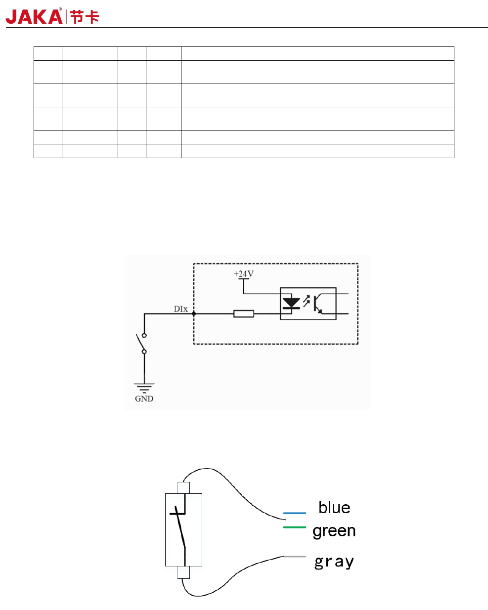
The digital input uses the optocoupler cathode input and is active low. Internally connected 4.7k resistors.
Figure 4-18
a)Type of the dry contact input:
Figure 4-19
The dry contact input (ie, switch input) is connected to the negative pole of the 24V power supply in TIO
(gray wire), and the other end is connected to the DI digital input (blue or green wire), as shown in Figure 4-19.
b) The input type is NPN
JAKA Zu 7 v2.5
34
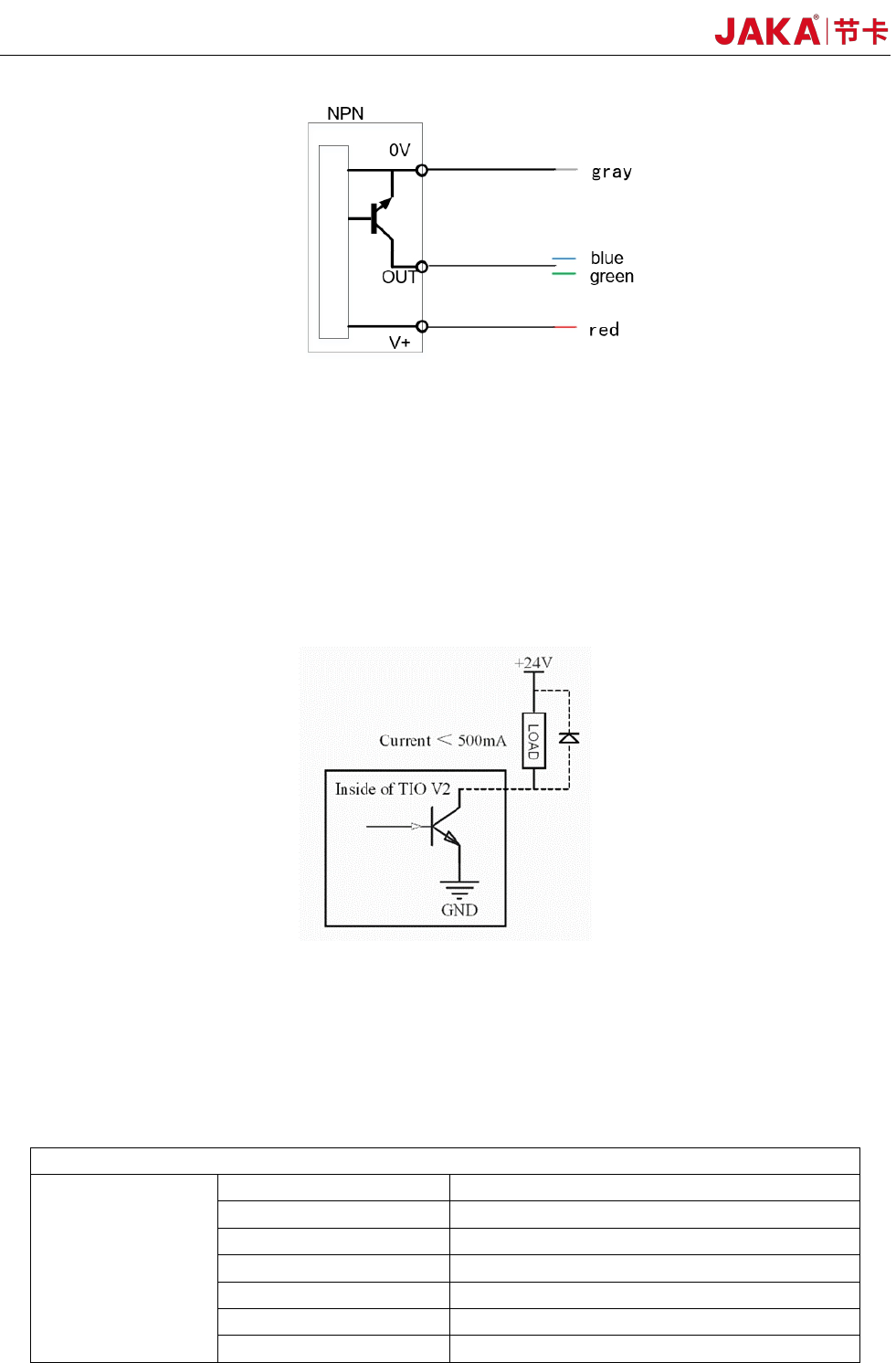
Figure 4-20
Figure 4-20 shows the block diagram of the NPN input device connection: the V + pin is connected to +
24V (red wire), the 0V pin is connected to the negative pole (gray wire), and the OUT pin is connected to DIx
(blue or green wire).
3. TIO digital output interface
The digital output interface uses an open collector output that supports up to 500mA of current capability.
Note: If an inductive load (such as a relay, electromagnet, DC motor, etc.) requires an external
freewheeling diode.
Figure 4-21
* Note: It is strongly recommended to use protection DIODES for the inductive loads (such as relays,
electromagnets, DC motors, etc.). Otherwise, this port may damage the hardware circuit
4.6 Technical Specifications
Product Features
Maximum payload 7kg
Weight (including cable) 22kg
Working radius 819mm
Repeatability
Degrees of freedom 6
Programming Graphical drag-and-drop programming
FlexPendant Type Mobile device (PAD/mobile)
1.JAKA Zu
®
7 Robot Technical Specifications:
Robot type: JAKA Zu
®
7
JAKA Zu 7 V2.5
JAKA Zu
®
7:±0.02mm
35
Collaborative operation
Cooperative operation according to
GB11291.1-2011 standard
Working range and
speed
Robot joint Working range Max speed
Joint1 ±270° 180°/s
Joint 2
-50°、+230° 180°/s
Joint 3 ±155° 180°/s
Joint 4 -85°,+265° 180°/s
Joint 5 ±270° 180°/s
Joint 6 ±270° 180°/s
Maximum speed of the
tool end
/ 2.5m/s
Physical properties
and others
Power consumption Average 350W
Temperature 0-50°C
IP classification IP54
Robot installation posture Install at any angle.
TIO Ports
2 digital input
2 digital output
1 analog input
TIO Power 24V
Base diameter 158mm
Material Aluminum alloy, PC
TIO Size M8
Robot connection cable
length
6m
2.Electrical cabinet technical specifications:
Electrical
cabinet
IP classification IP44
I/O ports
16 digital input
16 digital output
2 analog input/output
I/O power 24V
Communication TCP/IP, Mod bus TCP, Mod bus RTU
Power 100-240VAC,50-60Hz
Size
410*307*235(mm)(W*H*D)
Weight
12kg
Material Stainless steel alloy
JAKA Zu 7 v2.5