JAKA Zu 7电控柜V2.1-硬件手册(英文版).pdf - 第28页
26 Figure 4-5 Figure 4-6 3. Connec t the protective stop s witch Protective stop func tion, support autom atic recovery . The elec trical cabinet door s witch is an application case of the protec tion stop device, and th…
25
Figure 4-3
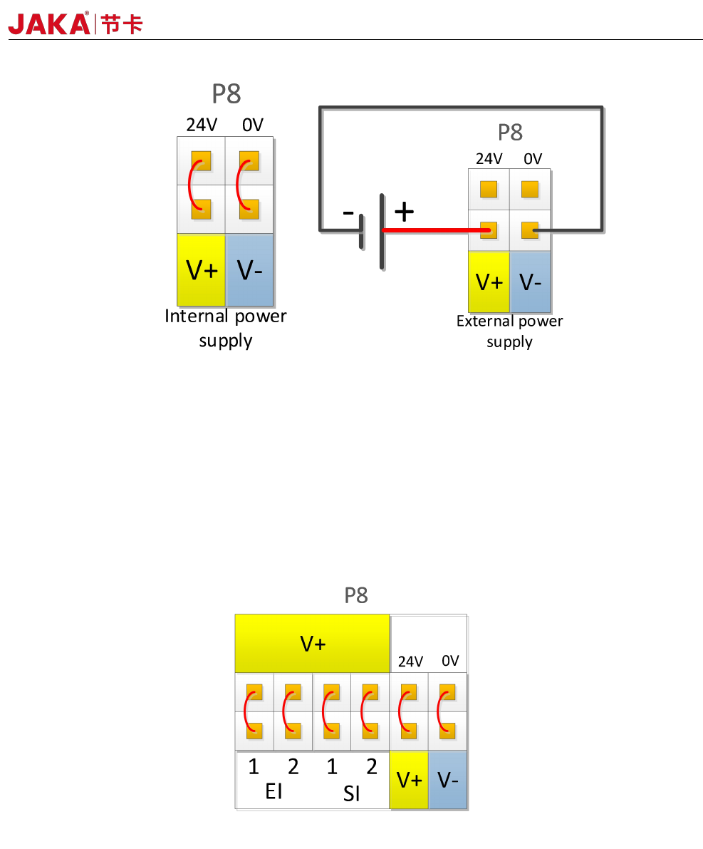
The electrical cabinet has a dedicated safety I/O interface, and the user can configure two functions:
emergency stop and protection stop. The function description is detailed in section 4.3.7. Here are some
examples of how safe I / O interface.
1. Factory configuration.
Users can use the robot without any additional safety equipment. If EI1~2 and SI1~2 are both connected to
V+, V+ is connected to 24V, and V- is connected to 0V, it indicates that 24V power is provided inside the
electrical cabinet. As shown in Figure 4-4.
Figure 4-4
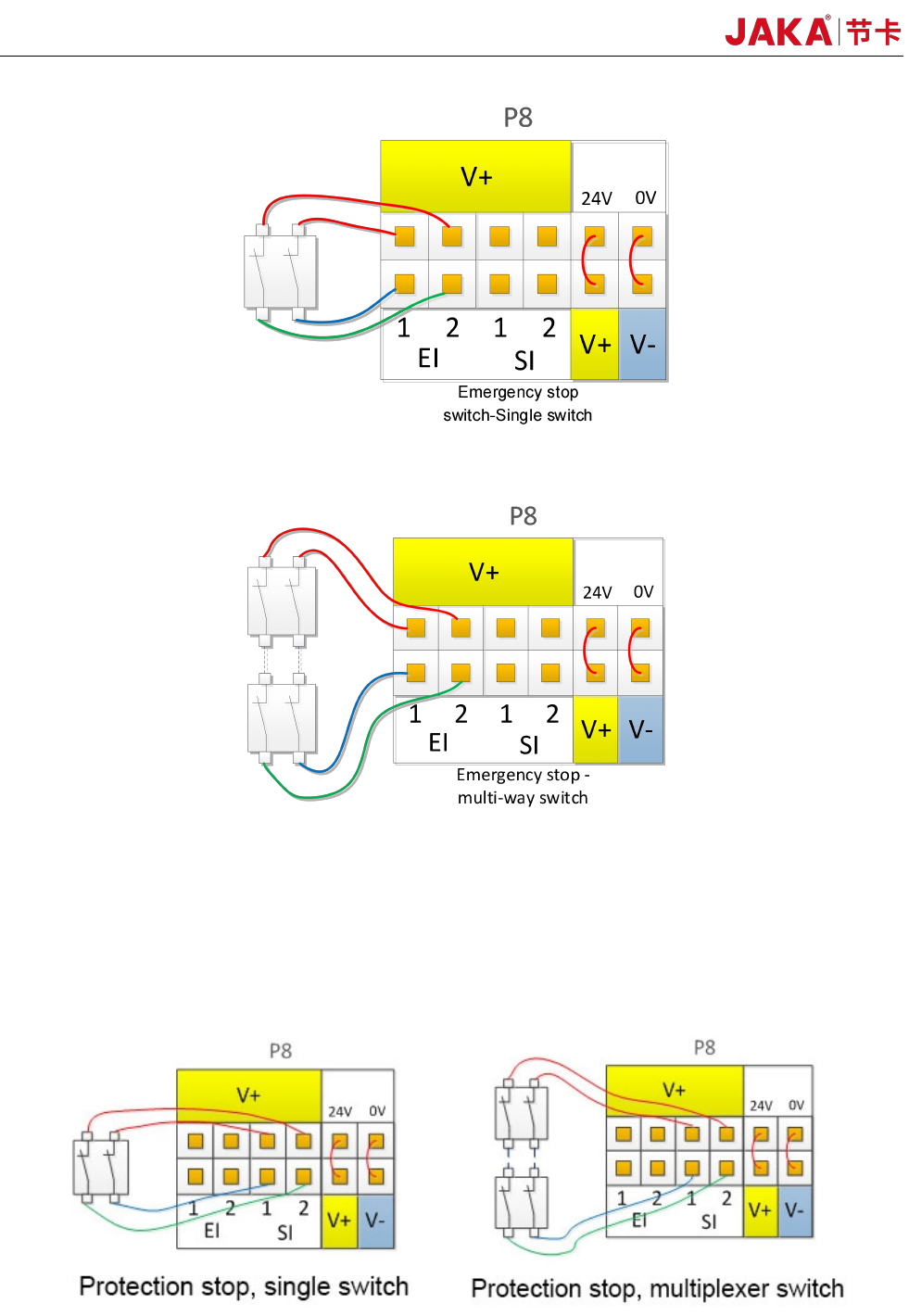
2、Connect the emergency stop switch.
The user needs to use one or more additional emergency stop or guard stop switches, please refer to Figure
4-5 and Figure 4-6 for wiring. Figure 4-5 and Figure 4-6 show how to use one or more emergency stop
switches. The example uses an internal 24V power supply and the user can also use an external 24V power
supply.
JAKA Zu 7 v2.5
26
Figure 4-5
Figure 4-6
3. Connect the protective stop switch
Protective stop function, support automatic recovery. The electrical cabinet door switch is an application
case of the protection stop device, and the robot stops when the electrical cabinet door is opened. The wiring
diagram is shown in Figure 4-7.
Fig 4-7
JAKA Zu 7 V2.5
27
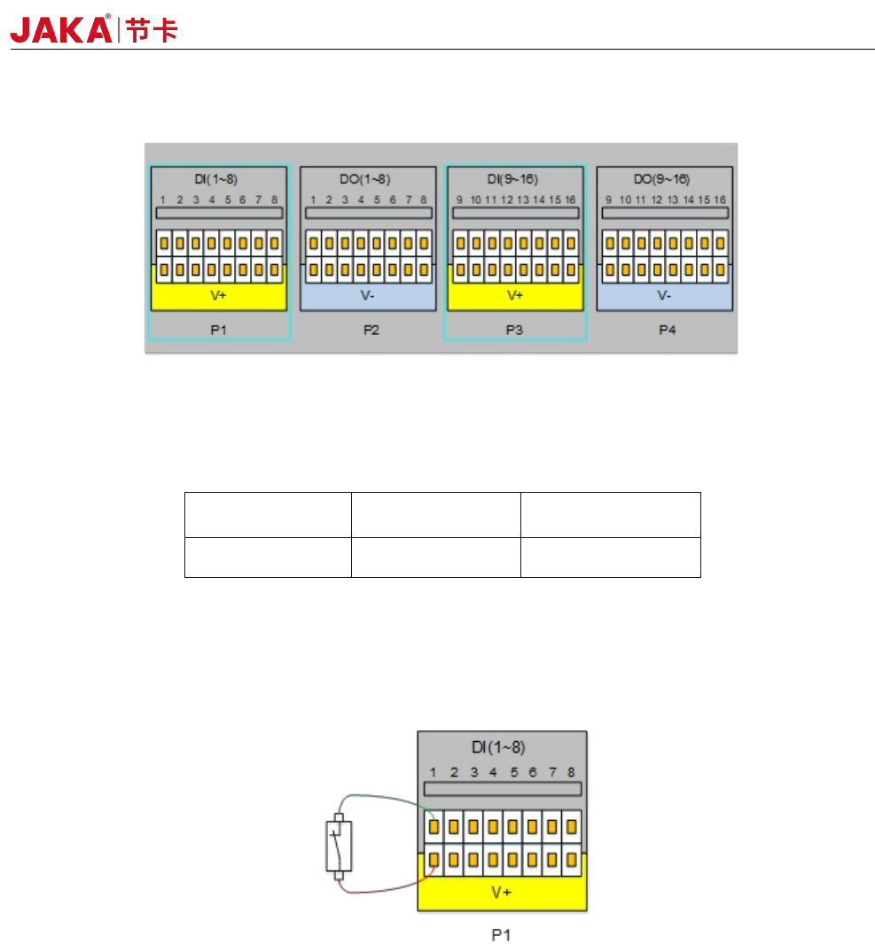
4.3.2 Digital Input (DI)
Fig 4-8
The electrical cabinet is equipped with 16 digital PNP type input(Active high) (DI1 ~ DI16) to support
isolated signal input. The level signal satisfies the IEC61131-2 (Type1/2/3) standard and is used to detect the
input signal level status.
V+
Voltage
Low range High range
24V
0~11V 15~24V
The V+ interface supports external 10~35V power input. The factory default uses internal 24V power
supply. The high level range is 15~24V, and the low level range is 0~11V.
Users can also connect DIx to V+ directly.
Different types of input signals have different connections. The specific connection methods are as follows:
a) Dry contact signal as input
Figure 4-9
During dry contact input, one of the wires is connected to V + and the other wire is connected to DIx. When
the circuit is on (as shown in the figure, the switch or relay is closed), the corresponding LED turns on. You can
also see the DIx status on the APP interface
b) PNP type signal as input
JAKA Zu 7 v2.5