SOM-1756-001.pdf - 第14页
[Comp Feed Rem Tm] Button When the value under "Feed Rem Tm" (the period of time during which the loaded components can be supplied, that is, the time in which the components are used up) becomes smaller than t…
*1 "ACV Function" Group Box
[Enable] Button
The ACV function becomes available.
[Disable] Button
The ACV function becomes unavailable.
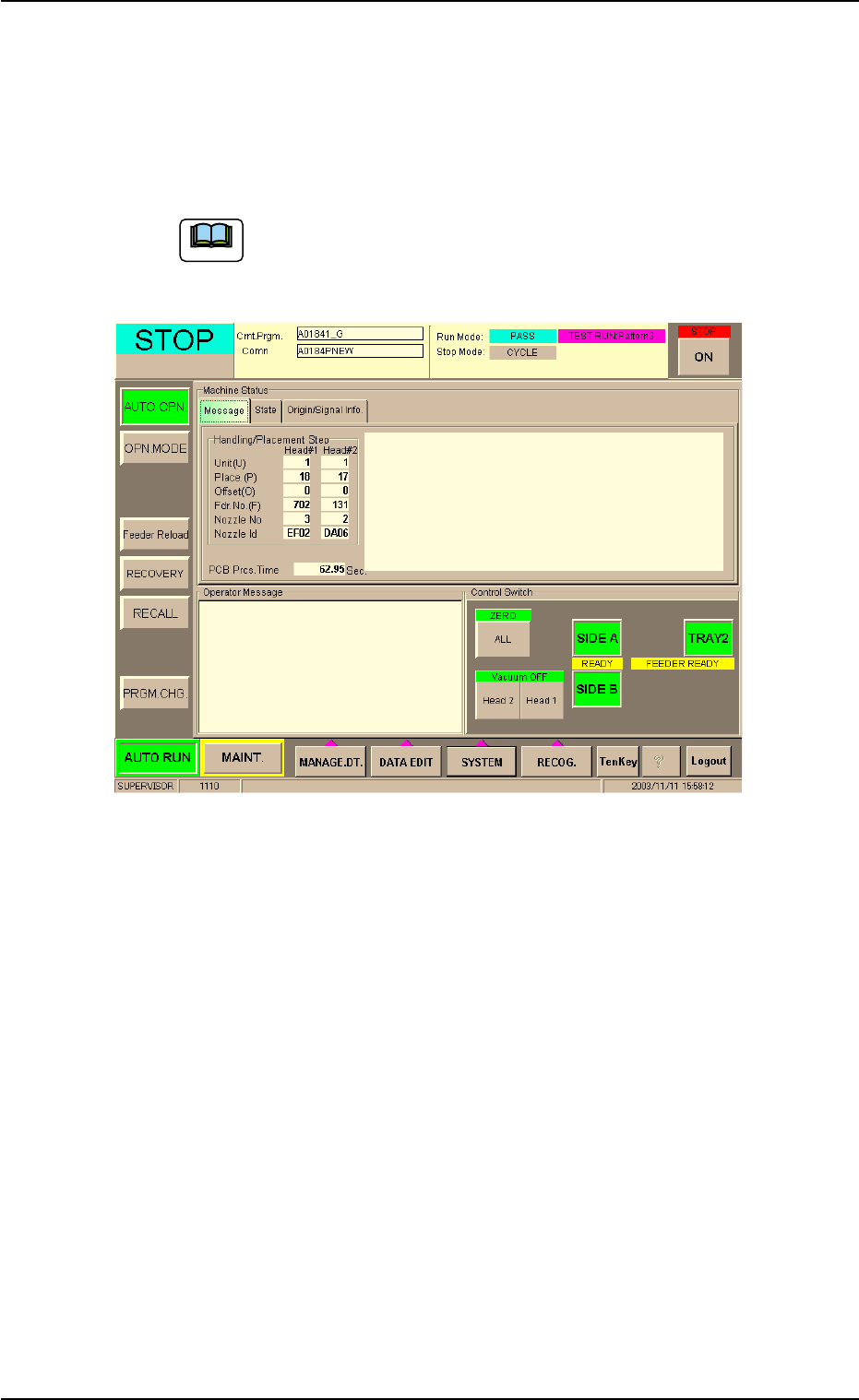
When "Enable" is set for the ACV function and the ACV
checking is started, "ACV Check Mode" appears in the "Op-
erator Message" pane of the "AUTO OPN." window.
Fig. 4
*2 "Alarm for Component Remainder" Group Box
An alarm for component remainder can be issued according to the
component remainder data which is read for each feeder.
The alarm message "Alarm for Component Remainder" appears in
the "Operator Message" pane and the feeder No. related to the alarm
can be checked in the "ACV Check Status" tab sheet.
[Comp Remainder] Button
When the value under "Comp Rem" becomes smaller than the
specified one in the "ACV Check Status" tab sheet, an alarm for
component remainder is issued.
[P.C.B. Remainder] Button
When the value under "PCB Rem" (the estimated number of P.C.B.'s
which can be produced using the loaded components) becomes
smaller than the specified one in the "ACV Check Status" tab sheet,
an alarm for P.C.B. remainder is issued.
8.1 "Opn. Mode" Tab Sheet
Note
0311-001 12 AIT01EGP

[Comp Feed Rem Tm] Button
When the value under "Feed Rem Tm" (the period of time during
which the loaded components can be supplied, that is, the time in
which the components are used up) becomes smaller than the speci-
fied one in the "ACV Check Status" tab sheet, an alarm for remain-
ing feed time is issued.
The time to be specified must be expressed in minutes.
As the time is calculated based on the time required to finish one
P.C.B., it may differ from the time in which all components are actu-
ally used up.
[Disable] Button
No alarm for component remainder is issued.
Data Input Range
0 to 9999
Depending on the option selected in the "Alarm for Component Re-
mainder" group box, each value represents number of components,
number of P.C.B.'s, or time (minutes).
When "Enable" is set for the ACV function, the alarm func-
tion for the component remainder becomes available.
*3 "Tray Function" Group Box
[Enable] Button
The ACV system is made available for the multi-layer tray feeder.
[Disable] Button
The ACV system is made unavailable for the multi-layer tray feeder.
When the tray ACV function is set unavailable, it is not checked if a
tray is set in a wrong position, regardless of the type of the pallet
(regardless of whether or not the pallet is provided with a bar code
label or a tag memory.) That is, the production becomes possible
without any checking for wrong tray settings.
When the tray function is set available ([Disable] Æ En-
able]), the number of remaining components cannot be
guaranteed in its accuracy. Therefore, the data must be
corrected to the actually specified number of components.
8.1 "Opn. Mode" Tab Sheet
Note
Note
0311-001 13 AIT01EGP
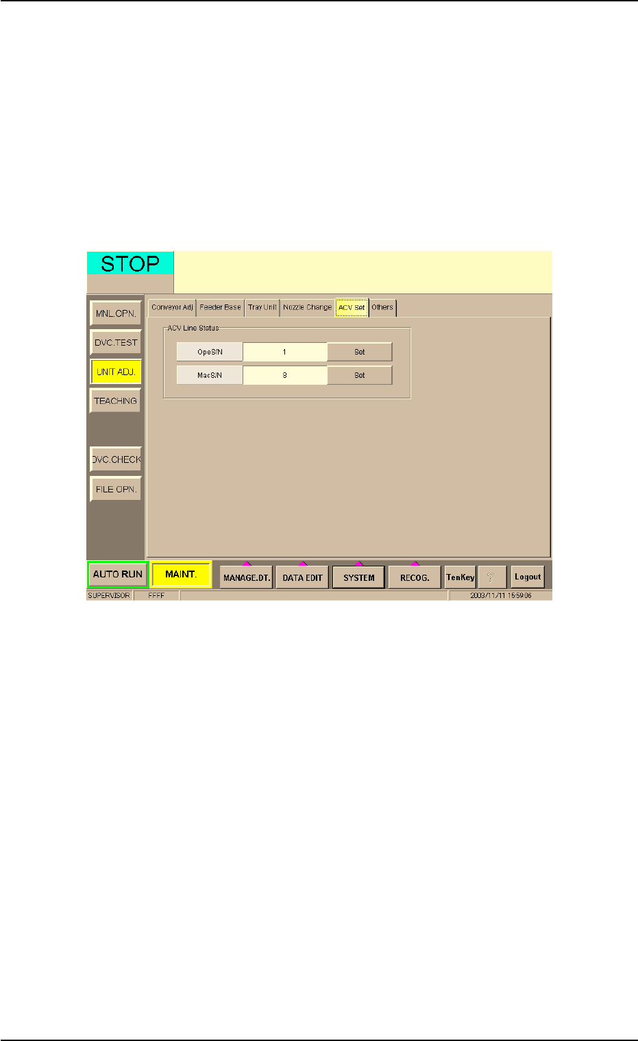
8.2 "ACV Set" Tab Sheet
This tab sheet enables the operator to check how the machine and the
ACV system are connected or reset the connection.
Do not use this function in normal cases.
• Sheet Layout
When the "ACV Set" tab is pressed in the "UNIT ADJ." window
(submenu), the following tab sheet appears.
Fig. 5
• Operation Procedure
(1) Check if the parameters in the "OpeS/N" and "MacS/N" text boxes
are correct or not.
(2) When a wrong number is used, press the [Set] button to communi-
cate with the ACV system.
8.2 "ACV Set" Tab Sheet
0311-001 14 AIT01EGP