SOM-1756-001.pdf - 第35页
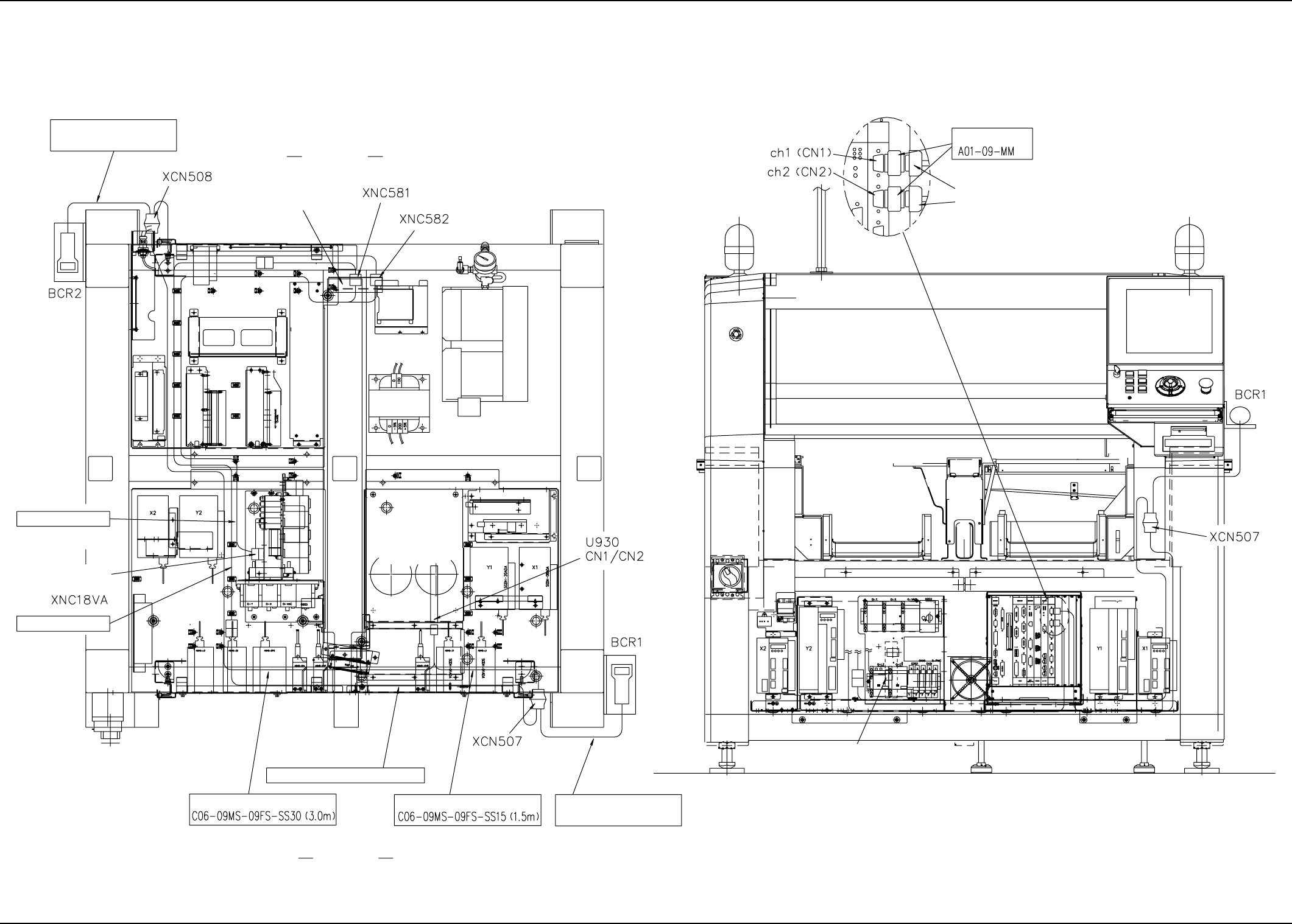
9.3 Cord Connection Diagrams 9.3.1 Cable Connection Diagram 9.3 Cord Connection Diagrams RS-232C 630 124 2576 630 124 2668 630 124 2668 630 124 3337 630 124 2583 100 V AC Power Supply Connector Panel Section VME Rack IX …
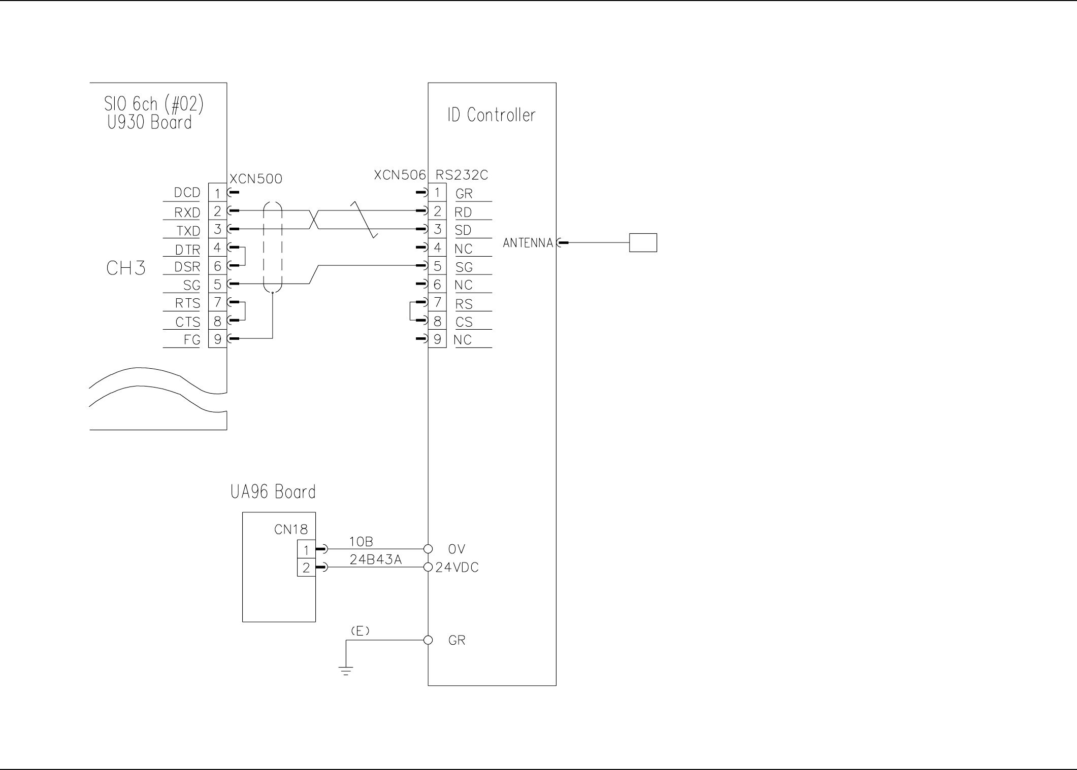
9.2.6 ID Controller Connection Diagram (For Pallet with Tag Memory)
9.2 Electrical Circuit Diagrams
Read/Write Head
0311-001 -(M750WC--A3104) 33 AIT01EGP
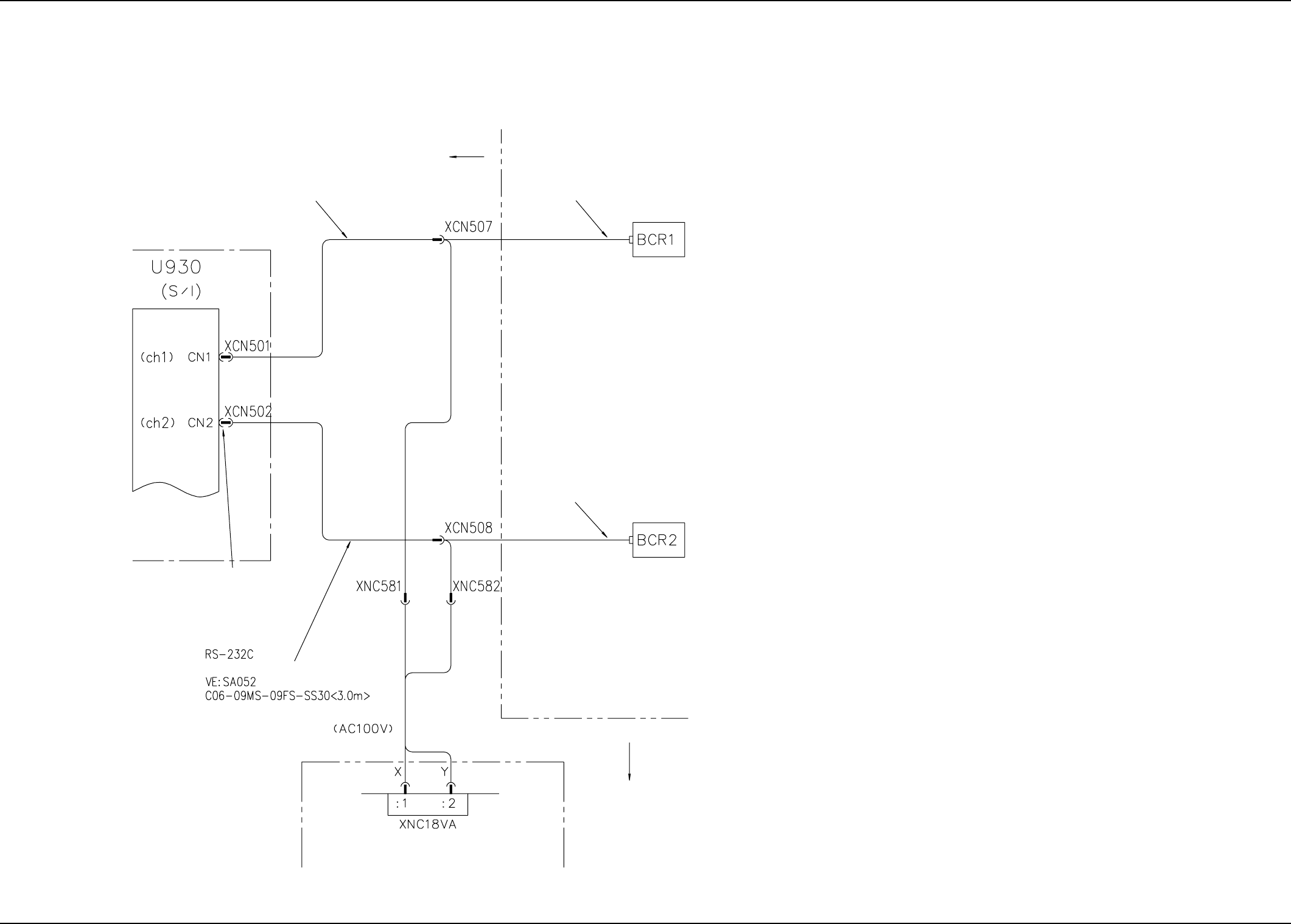
9.3 Cord Connection Diagrams
9.3.1 Cable Connection Diagram
9.3 Cord Connection Diagrams
RS-232C
630 124 2576
630 124 2668
630 124 2668
630 124 3337
630 124 2583
100 V AC Power Supply
Connector Panel Section
VME Rack
IX (Main Body)
Conversion Connector
(M013: MISUMI CORP.)
To Operation Monitor on Side
A
To Operation Monitor on Side B
IX (Main Body)
0311-001 -(M750JVE-A3101) 34 AIT01EGP
9.3.2 Cable Connection
9.3 Cord Connection Diagrams
630 124 2668
630 124 2583
630 124 2576
630 124 2668
630 124 3337
LS1902T-RS-DOS/V Setting
Side A
This is replaced with
a new bracket.
(VB Block: Part No. 057)
(An additional
socket is used.)
(An additional
socket is used.)
Two cables (both + and - sides)
must be drawn out.
100 V AC Cable Connections
(Internal Work)
100 V AC Cable Connections
(Internal Work)
100 V AC
Connector Panel
Section
VME Rack
100 V AC Cable (The AC adaptor must be modified.)
Side B
100 V AC
Connector Panel Section
Plane B Side of Machine (Front View)
Conversion Connector
XCN501 (for BCR1)
XCN501 (for BCR2)
Area inside VME Rack
U930 (6-port serial IF) Board
Details
LS1902T-RS-DOS/V Setting
0311-001 A(M750JVC-A3102) 35 AIT01EGP