SOM-1756-001.pdf - 第34页
9.2.6 ID Controller Connection Diagram (For Pallet with T ag Memory) 9.2 Electrical Circuit Diagrams Read/Write Head 031 1-001 -(M750WC--A3104) 33 AIT01EGP
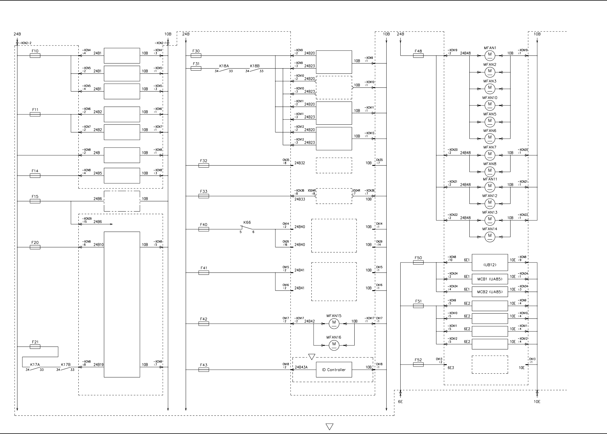
9.2.5 Power Circuit Diagram (3) (For Pallet with Tag Memory)
9.2 Electrical Circuit Diagrams
S
Input/Output Machine
I/F Board (UA53)
NC1-Axis
Motor Driver
NC2-Axis
Motor Driver
Liquid Crystal Monitor
(Rear View)
Liquid Crystal Monitor
(Front View)
Lighting Control Board
(UA75)
Motor Relay Board
(UA93)
Relay Board
(UA96)
Brake Control Relay
Wiring Section
I/O Main Board
(UB12)
Sensors and Indicators
For Beam Sensor 2
For Sensor on
Frame Top
For Panel 1
For Panel 2
For Cover Top
For Electromagnetic
Valve
DC Load
Power Supply 1
DC Load
Power Supply 2
Note: The areas surrounded by a broken line belong to the relay board (UA96).
Right Door Fan Motor
Left Door Fan Motor
Feeder Base #1
Feeder Base #2
Feeder Base #3
Feeder Base #4
(Option)
(Multi-Layer Tray 1 (Option))
(Multi-Layer Tray 2 (Option))
Feeder
Power Supply #1
(Vertical Bend Detection (Option))
(BCR Option)
Note1
Frame Lower R Side 1
Fan Motor
Frame Lower R Side 2
Fan Motor
Frame Lower R Side 3
Fan Motor
Frame Lower Front Fan Moto
r
Frame Lower L Side 1
Fan Motor
Frame Lower L Side 2
Fan Motor
Frame Lower L Side 3
Fan Motor
Frame Lower L Side 4
Fan Motor
Upper Exhaust Fan Motor 1
on Frame
Upper Exhaust Fan Motor 2
on Frame
Upper Exhaust Fan Motor 4
on Frame
Upper Exhaust Fan Motor 3
on Frame
I/O Main Board
Feeder Base #1
Feeder Base #2
Feeder Base #3
Feeder Base #4
(Vertical Bend Detection (Option))
Feeder
Power Supply #2
S
The -marked area is specially specified.
0311-001 -(M750WB--A3106) 32 AIT01EGP
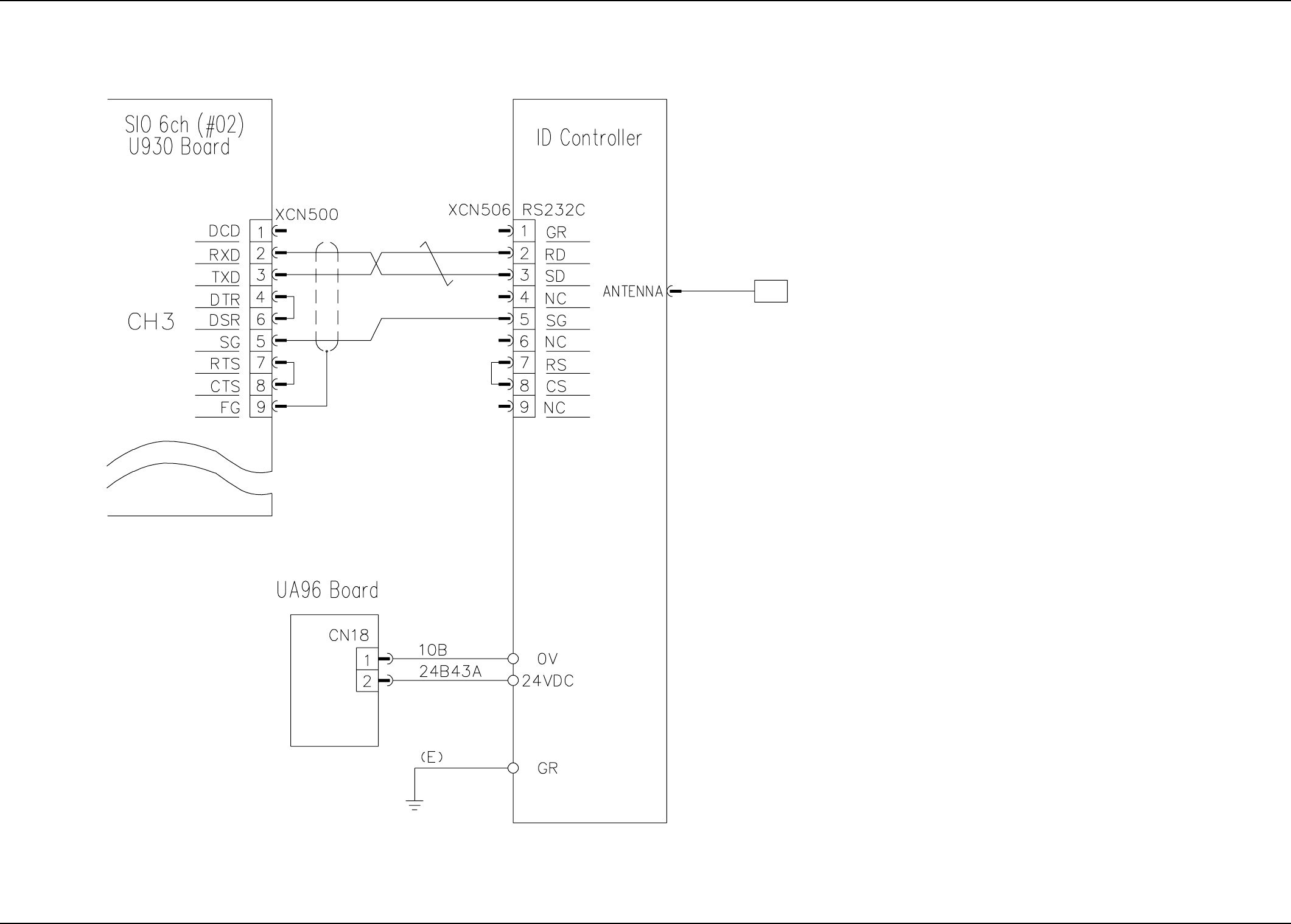
9.2.6 ID Controller Connection Diagram (For Pallet with Tag Memory)
9.2 Electrical Circuit Diagrams
Read/Write Head
0311-001 -(M750WC--A3104) 33 AIT01EGP
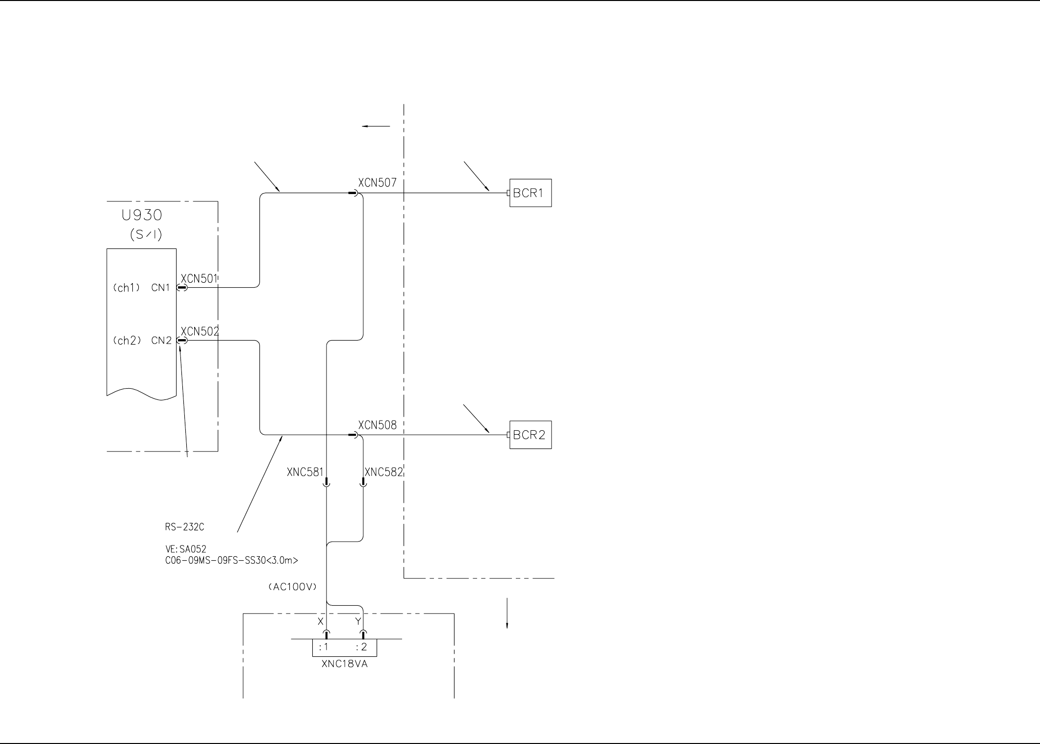
9.3 Cord Connection Diagrams
9.3.1 Cable Connection Diagram
9.3 Cord Connection Diagrams
RS-232C
630 124 2576
630 124 2668
630 124 2668
630 124 3337
630 124 2583
100 V AC Power Supply
Connector Panel Section
VME Rack
IX (Main Body)
Conversion Connector
(M013: MISUMI CORP.)
To Operation Monitor on Side
A
To Operation Monitor on Side B
IX (Main Body)
0311-001 -(M750JVE-A3101) 34 AIT01EGP