SOM-1756-001.pdf - 第31页
9.2.3 Bar Code Reader Connection Diagram 9.2 Electrical Circuit Diagrams 100 V AC Connector Panel T o the unit on Side A Side A Side B 031 1-001 -(M750WC--A3105) 30 AIT01EGP
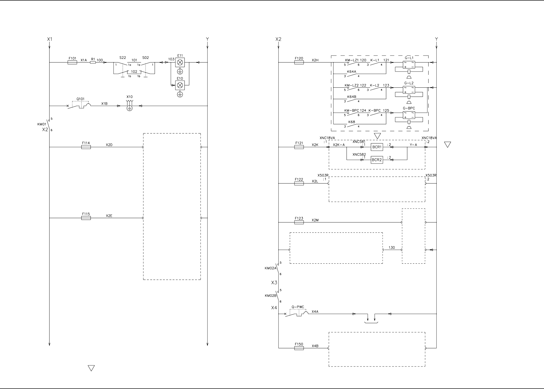
9.2.2 Power Circuit Diagram (2)
9.2 Electrical Circuit Diagrams
S
S
S
The -marked area is specially specified.
Lighting for Operation
(Front View)
Lighting for Operation
(Rear View)
Console Power Supply
For Fan Motor
(Reserved)
For Fan Motor
(Reserved)
Multi-Layer Tray (2)
(For HUB)
(For Main Body)
For Vertical Bend Detection
(Option)
L1-Axis Brake OFF
L2-Axis Brake OFF
BPC-Axis Brake OFF
Bar code scanner
(Sides A and B) Power Supply
Multi-Layer Tray (2)
Elevator Brake OFF
(Option)
Power Supply for
Vertical Bend Detection
Power Supply for
Vertical Bend Detection
PWC-Axis Drive
Recycle Conveyor Motor
To APMD-PWC
(Option)
0311-001 -(M750WB--A3107) 29 AIT01EGP
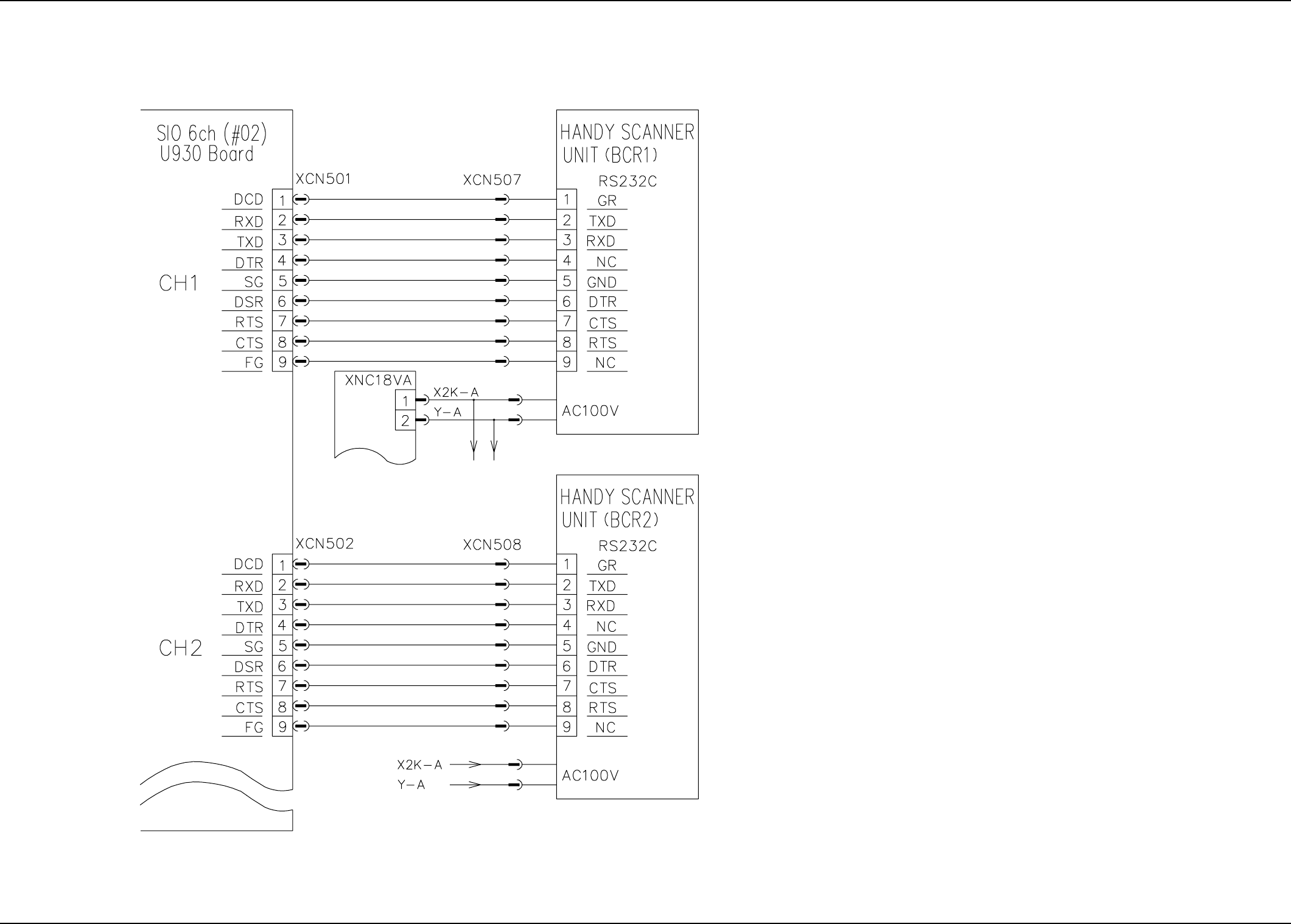
9.2.3 Bar Code Reader Connection Diagram
9.2 Electrical Circuit Diagrams
100 V AC
Connector Panel
To the unit on Side A
Side A
Side B
0311-001 -(M750WC--A3105) 30 AIT01EGP
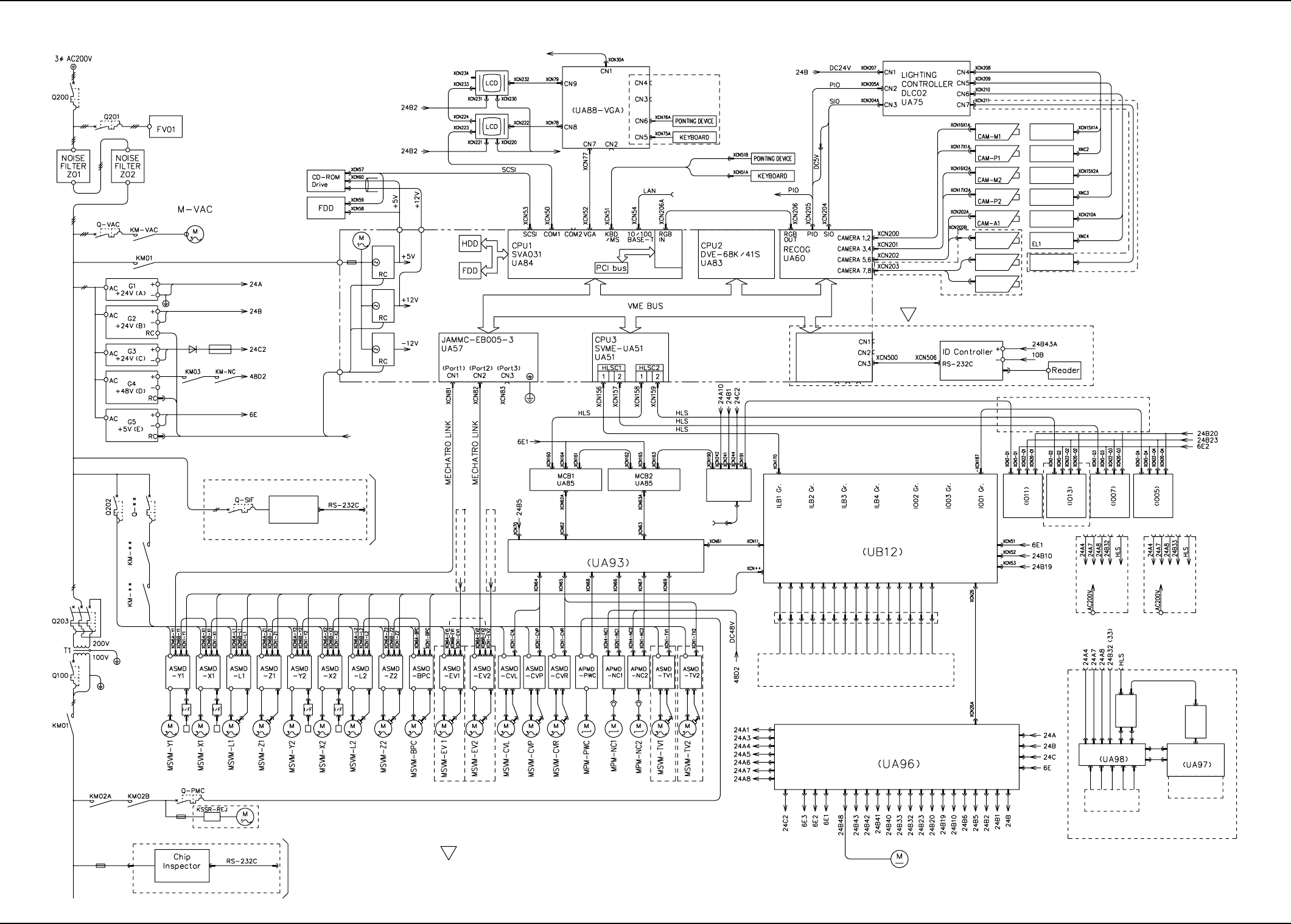
9.2.4 Integrated Block Connection Diagram (For Pallet with Tag Memory)
9.2 Electrical Circuit Diagrams
S
Lightning Surge
Vacuum Pump M
For Safety Circuit
For I/O
DC 24 V for Loads
DC 24 V for Devices
For Input/Output
Machine Interface
For NC-Axis Driver
For P.C.B. 5V
From Relay Board
To I/O Relay Board
VGA Distributor
(Changeover to Option)
To the service
panel
Video
Capture
Serial I/O
Control Board
U930
(Optional Board)
Movable Recognition
Camera 1
Fixed Recognition
Lighting
EL-A1
P.E.C. Recognition
Camera 1
Fixed Recognition
Camera
Movable Recognition
Camera 2
P.E.C. Recognition
Camera 2
Movable Recognition
Lighting 1
EL-M1
P.E.C. Recognition
Lighting 1
EL-P1
Movable Recognition
Lighting 2
EL-M2
P.E.C. Recognition
Lighting 2
EL-P2
Camera (Option)
Offset Lighting
Fixed Recognition
Lighting
Lighting (Option)
To I/O Relay Board
To I/O Relay
Board
System Rack
I/O&DC24V
The connectors must be separated or a branching unit must be added when the option is used.
(For each axis)
(For each axis)(For each axis)
ID Controller
for SIF
Option for SIF
To the serial I/O
control board
From Relay Board (UA98)
Multi-Layer Tray Feeder (Option)
From Relay Board (UA98)
Multi-Layer Tray Feeder (Option)
Pulse Train
Pulse Train
I/O Main Board
Motor Relay Board
To the input/output
machine interface
panel
UA53
Input/Output
Machine
I/F Board
(IO10)
Relay
Connector
Feeder
Base #1
Feeder
Base #2
Feeder
Base #3
Feeder
Base #4
Multi-Layer Tray
Feeder 1
Multi-Layer Tray
Feeder 2
(Option) (Option)
S
Loads and Sensors
UA78-2
IL Board
UA76- 4
IL Board
Relay Board
Cooling Fan
Relay Board
Switch Board
Luminous Switch
Loads and Sensors
Multi-Layer Tray
(Option)
Multi-Layer Tray (Option) Multi-Layer Tray (Option)
The -marked area is specially specified.
Linear Scale Y1
Linear Scale X1
Linear Scale Y2
Linear Scale X2
Slip Ring
Slip Ring
Recycling CV (Option)
(Main Body)
Option for Vertical Bend
To the serial I/O
control board
(Fach Axis)
0311-001 -(M750WA--A3102) 31 AIT01EGP