Istruzioni d´uso_HF3_14_it.pdf - 第604页
11 2KE0041502 - englisch_BA 04.1 1.2010 ENGLISH 2.2 W ater Circuit (See also flow diagram of pipes and instruments) 2.2.1 Single Circuit System with T ank The water circuit with its integrated tank is designed as a syste…
10
2KE0041502 - englisch_BA
04.11.2010
ENGLISH
2. DESCRIPTION OF THE PROCESS COOLER
The process cooler is a unit ready for plug-in and is equipped with refrigeration and water
circuits including all fittings and regulating/control devices required for automatic operation.
The heat extracted from the water is given off to the ambient air via the refrigeration circuit – by
means of the fans.
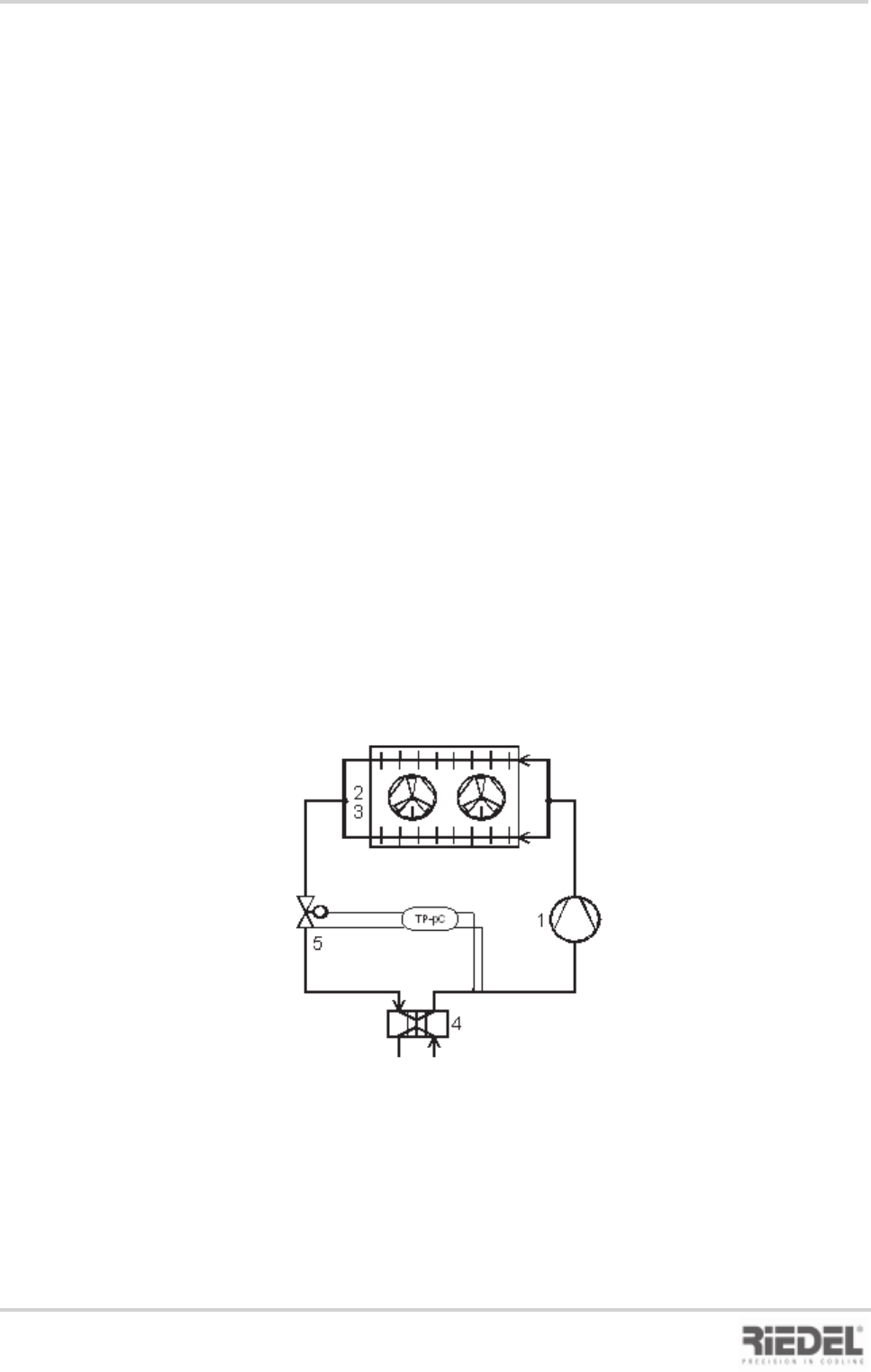
2.1 Refrigeration Circuit
The refrigeration circuit is a closed-loop system in which the refrigerant circulates as the
working medium.
The water heated by the equipment to be cooled is re-cooled in the evaporator (3). The liquid
refrigerant is thereby passed through the piping in a counter-flow arrangement with respect to
the water. The refrigerant evaporates as it takes up the waste heat from the cooling water of the
equipment to be cooled.
The vaporised refrigerant is drawn in by the compressor (1) and is then compressed (rise in
pressure and temperature). The refrigerant also absorbs the heat of the compressor motor; this
heat is given off to the surrounding air by the condensers (2) - in the form of waste heat –by
means of the fan.
The refrigerant is thus liquefied and is passed to the inlet of the expansion valve (4) via the
liquid receiver, the shut-off valve, the filter drier and the sight glass. The expansion valve permits
liquid refrigerant to enter the evaporator as a function of the temperature.
The circuit is now complete.
Block flow diagram, refrigerant circuit
2. Description of the Process Cooler

11
2KE0041502 - englisch_BA
04.11.2010
ENGLISH
2.2 Water Circuit
(See also flow diagram of pipes and instruments)
2.2.1 Single Circuit System with Tank
The water circuit with its integrated tank is designed as a system open to the atmosphere. The
constancy of the water outlet temperature is governed by the water volume inside the tank. The
pump conveys the water out of the tank to the equipment to be cooled and back to the tank via
the evaporator.
2.3 Cooling Air Supply
The heat transferred to the evaporator upon cooling the water as well as the heat of the
compressor motors are absorbed by the refrigerant and given off to the cooling air in the
condenser.
As cooling air the ambient air is used which is drawn through the condenser by the fan(s),
warmed and then discharged in upward direction
It must be ensured that the cooling air can be drawn in and discharged without any
obstructions and adequate air changes for heat dissipation away from the installation
site of the process cooler take place.
(see also Section Installation)
2. Description of the Process Cooler

12
2KE0041502 - englisch_BA
04.11.2010
ENGLISH
2.4 Safety Devices
The process cooler is equipped with the following safety devices:
High-pressure control (HP)
The high-pressure control is designed to protect the process cooler against extremely high
operating pressure in the refrigeration cycle.
In the event of a malfunction, the HP control switches the process cooler off, and the
malfunction is indicated on the control panel.
The process cooler cannot be restarted until the pressure has dropped to the preset pressure
difference and the Reset button on the pressostat has been pressed.
The high-pressure pressostat can be accessed from the service side.
2.5 Monitoring Devices
Low-pressure control (LP)
The low-pressure control protects the process cooler against extremely low operating pressure
in the refrigeration cycle.
In the event of a malfunction, the control switches off the process cooler, and the malfunction
is indicated on the control panel.
Restarting of the process cooler is effected automatically as soon as the pressure has risen
by the preset pressure difference.
Winter starting aid
The winter starting aid is designed to prevent any low pressure malfunctions in low ambient
temperatures during the start-up phase of the cooling operation until normal operating
conditions have been established.
Compressor overheat protection
The compressor is equipped with an overheat protection (thermal contact, Klixon). In the event
of an increase in motor current in conjunction with a rise in winding temperature, the overheat
protection trips, and the compressor is switched off. The overheat protection resets itself
automatically after the windings have cooled down. The malfunction is indicated on the control
panel.
Thermal contact – fan motor
In the event of an increase in motor current in conjunction with an increase in winding
temperature, cooling operation is switched off by the thermal contact.
This malfunction is indicated on the control panel.
Circuit breakers (compressor, fan, pump)
In the event of an increase in motor current or in the case of short circuits, the circuit breaker
trips and interrupts the power supply.
Such malfunctions are indicated on the control panel.
The circuit breakers are located in the control cabinet.
2. Description of the Process Cooler