Specification SIPLACE CA-Series2011版.pdf - 第11页
11 Machine Description Technical Data - SWS T echnical dat a Flip Chip Die Attach X/Y accuracy a a) Calculated with glass die on glass plate - SIPLACE MAC test ± 10 µm at 3 ± 10 µm at 3 Placement pe rformance ( IPC) …
10
Machine Description
Machine Performance
The following table lists the benchmark values (as defined in "Scope of Service and
Delivery SIPLACE CA") for SMT placement in each placement area. As the benchmark
test for the TwinHead and the C&P heads uses different components, the benchmark
values for the TwinHead and C&P heads must be specified separately. However, the
joint component spectrum can still be processed by both the TwinHead and the Col-
lect&Place heads in the same production environment.
Placement heads in placement area (PA) Placement rate [comp./h]
SMD Application
C&P20CA and C&P20CA 40,000 cph ± 3 %
C&P12 and C&P12 26,400 cph ± 3 %
C&P12 and C&P6 20,300 cph ± 3 %
C&P6 and C&P12 20,300 cph ± 3 %
C&P6 and C&P6 18,300 cph ± 3 %
TH and TH 5,800 cph ± 3 %
C&P12 and TH C&P12: 14,000 cph ± 3 %
TH: 3,300 cph ± 3 %
C&P6 and TH C&P6: 9,800 cph ± 3 %
TH: 3,300 cph ± 3 %
C&P20CA 20,000 cph ± 3 %
C&P12 14,000 cph ± 3 %
C&P6 9,800 cph ± 3 %
TH 3,700 cph ± 3 %
Die placement depends on several process-specific parameters. The expected
throughput can be individually calculated on request.
The benchmark values for one SWS and a die size of 1x1mm are:
In “Flip Chip” mode: 9.000 dies / h without flux dipping
In “Flip Chip” mode: 6.000 dies / h with flux dipping
In “Die Attach” mode (on request): 6.000 dies / h
See also page 11.

11
Machine Description
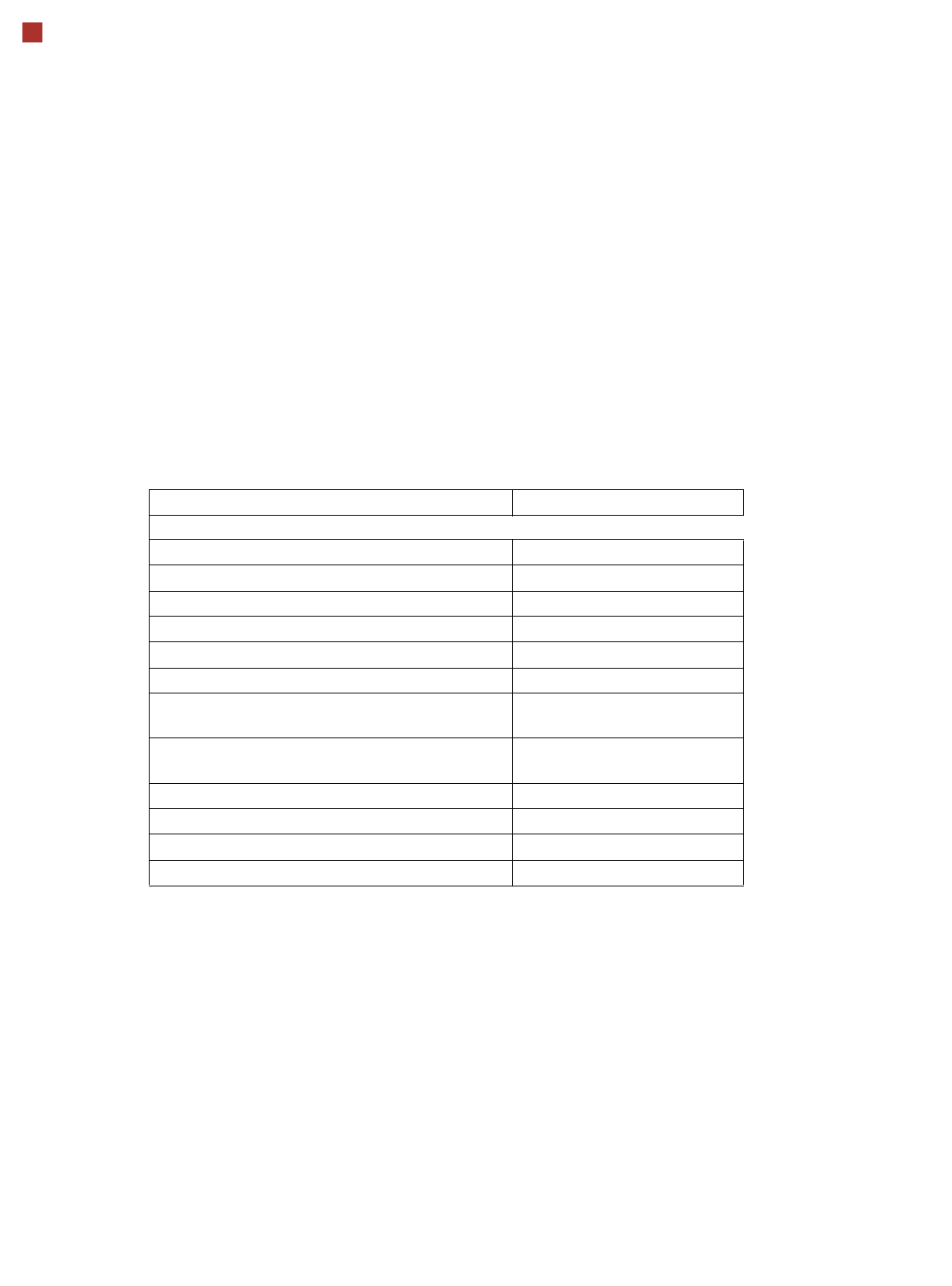
Technical Data - SWS
Technical data Flip Chip Die Attach
X/Y accuracy
a
a) Calculated with glass die on glass plate - SIPLACE MAC test
± 10 µm at 3 ± 10 µm at 3
Placement performance (IPC)
b
b) Calculated with the SIPLACE CP20-CA head
9,000 dies/h
(without flux dipping)
6,000 dies / h
6,000 dies/h
(with flux dipping)
Die sizes
c
c) Calculated with the SIPLACE CP20 and CP12 head. Alternative SIPLACE placement heads available for
greater component spectrum.
0.8 mm to 18.7 mm 0.8 mm to 18.7 mm
Minimum die thickness (silicium) 50 µm 50 µm
Minimum bump size 50 µm n/a
Minimum bump grid 100 µm n/a
SIPLACE Wafer System SWS Horizontal system, automatic wafer change,
MCM
SWS wafer size 4“ to 12“
Wafer frame 12“/8“
Wafer frame area 0 mm to 8 mm
Die Ejection System Programmable ejection speed
Linear Dipping Unit LDU Individually programmable speed
Flux viscosity 3,000 to 100,000 cPs
Accuracy of flux height ± 5 µm
Programmable set-down force 1.0 N to 5.0N (depends on head)
Substrate types FR4, ceramic, flex, boats, 8"/12" wafer etc.
Substrate thickness 0.3 mm to 4.5 mm
Substrate size 50 mm x 50 mm to 508 mm x 610 mm
12
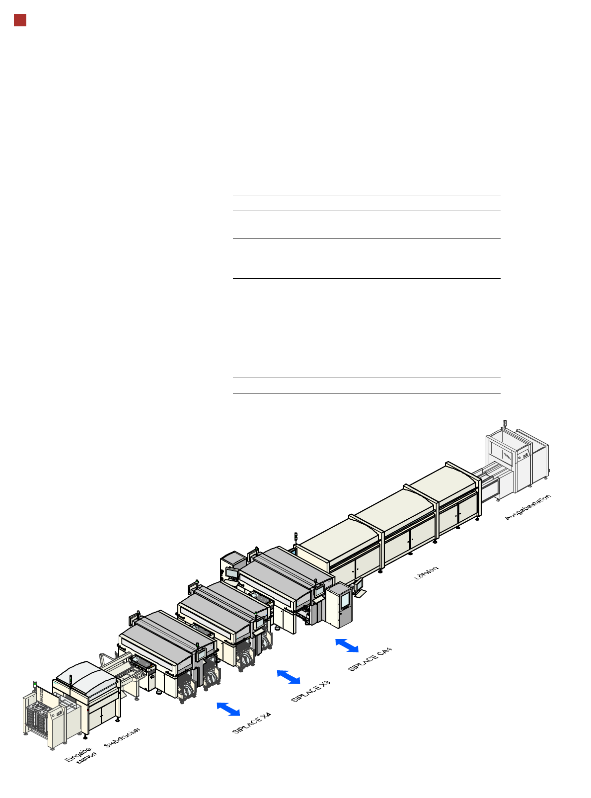
Line Concept
Description
Flexibility, modularity, com-
pact dimensions and high
power density are the hall-
marks of the new SIPLACE
concept. It allows a produc-
tion line to be individually
configured from identical and
different modules. If the pro-
duction requirements
change, the individual place-
ment machines are so com-
pact that they can be recom-
bined quickly and easily.
Operated together with the
SIPLACE X series, the
SIPLACE CA machine al-
lows you to individually con-
figure your production line
with both identical and differ-
ing modules. If the produc-
tion requirements change,
the individual placement ma-
chines are so compact and
can be combined with such
flexibility that they can be re-
combined quickly and easily.
The SIPLACE CA family has
the optimum placement sys-
tem for each individual per-
formance requirement.
System SIPLACE Placement lines
Placement
module
SIPLACE CA4/CA3, SIPLACE X series,
SIPLACE SX1/SX2,SX4
Peripheral
modules
Input/output stations, screen printer, sol-
dering furnace, inspection places etc.
available from SIPLACE
PCB conveyor Single and dual conveyor with auto-
matic width adjustment unit;
Dual conveyor in single conveyor mode
"Wide board" mode with "long board"
option and a combination of these for
both PCB conveyors. The maximum
PCB width is determined by the module
with the smallest PCB conveyor width.
Space required 6.7 m² per CA4 module