Specification SIPLACE CA-Series2011版.pdf - 第18页
18 Placement heads 6 Segment Collect&Place CA Head for High Speed IC Placement Description The 6 segment Collect&Place head also operates acco rding to the Collect&Place principle. With the help of a h igh-re…
17
Placement heads
12 Segment Collect&Place CA
Head for Very High Speed Placement
Description
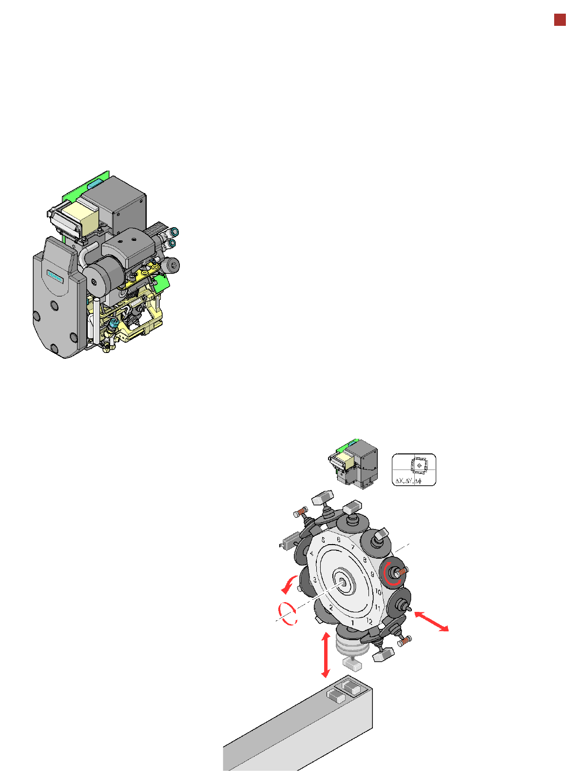
The 12 segment Collect&
Place head operates accord-
ing to the Collect&Place prin-
ciple i.e. twelve components
are picked up from the place-
ment head within a single cy-
cle, are optically centered on
the way to the board and are
also rotated into the required
placement position. Lastly,
the air kiss sets down the
component gently and accu-
rately on the board.
Checking and self-learning
functions
Various control and self-
learning functions enhance
the reliability of the Col-
lect&Place head.
• For example, vacuum
checks at the nozzles indi-
cate whether the compo-
nent (CO) was picked up
or set down correctly.
• A digital component cam-
era on the placement head
determines the precise
position of each compo-
nent at the nozzle.
• Deviations from the pickup
position are corrected be-
fore placement.
• The package form is also
checked and the compo-
nent is not placed if the
geometric data thus deter-
mined differs from the pro-
grammed data.
The vertical axis for picking
up and placing the compo-
nent works in sensor stop
mode, This sensor stop
method compensates differ-
ences in height during pickup
and any unevenness of the
PCB surface during place-
ment. In addition to the vacu-
um check, an optional com-
ponent sensor can be used
to check the component
presence at the nozzle.
The use of a component sen-
sor is recommended in par-
ticular for placement with
small components, such as
0201.
The 12 segment Collect&
Place head is fitted with a
high-resolution component
camera as a default. With the
help of this camera, the 12
segment Collect&Place head
can optically center and
place components of size
0201, up to
18.7
mm x18.7mm
(SWS: 0.8 mm x 0.8 mm up
to 12 mm x 12 mm, larger
dies on request.
Component vision module
DP axis:
Rotate component into
placement position
Pull off or
insert sleeve
Z axis:
Pick up component
or place it
DR axis:
Star rotation
Reject
component
18
Placement heads
6 Segment Collect&Place CA
Head for High Speed IC Placement
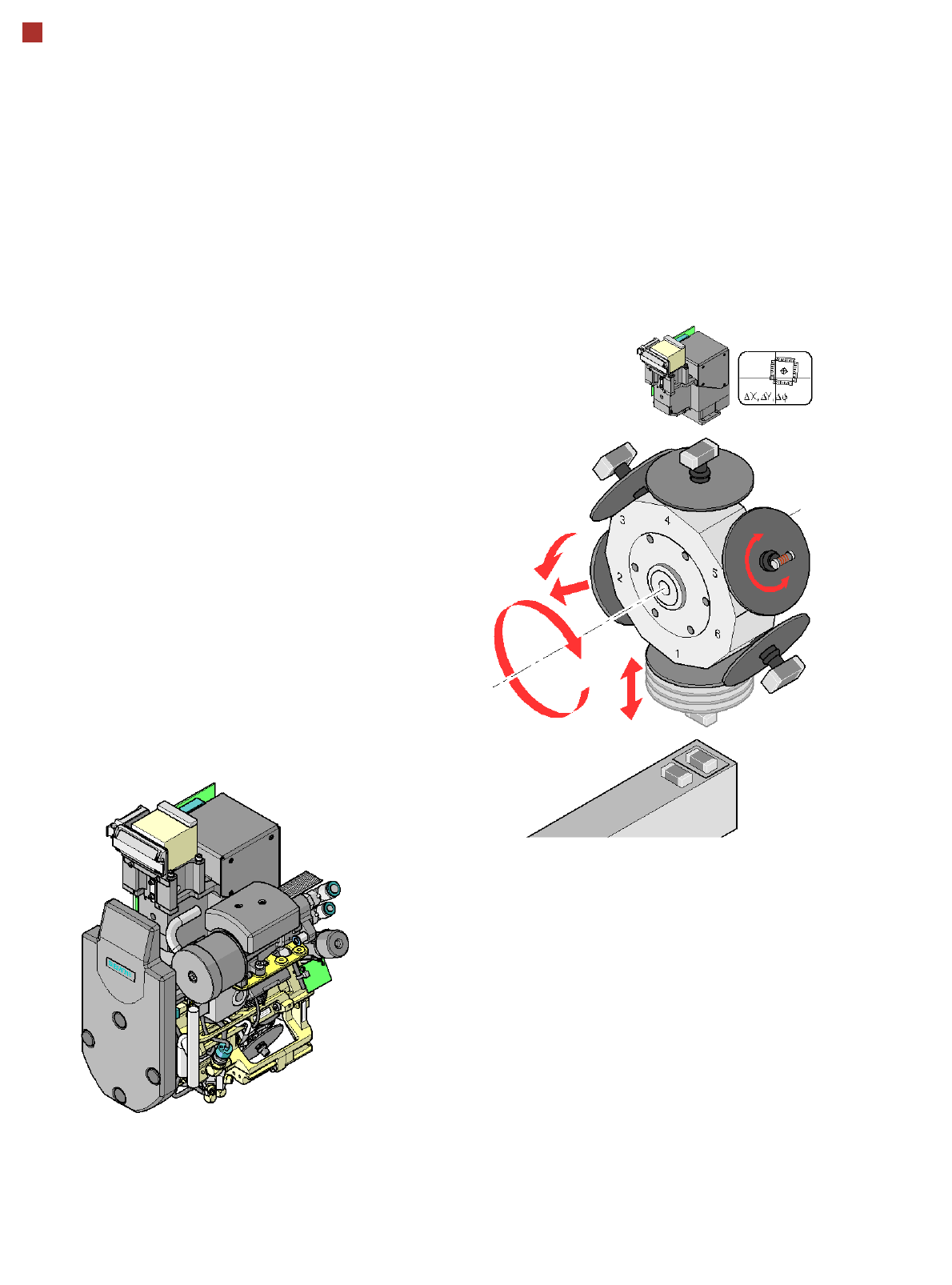
Description
The 6 segment
Collect&Place head also
operates according to the
Collect&Place principle. With
the help of a high-resolution,
digital component camera,
the 6 segment Collect&Place
head can optically center and
place components of size
0201, up to 27 mm x 27 mm.
Checking and self-learning
functions
The control and self-learning
functions, described on page
17 for the 12 segment
Collect&Place head, also
apply to the 6 segment Col-
lect& Place head.
Component vision module
DP axis:
Rotate component
into placement posi-
tion
Z axis:
Pick up component or place it
DR axis:
Star rotation
Reject component,
pull off or
insert sleeve
19
Placement heads
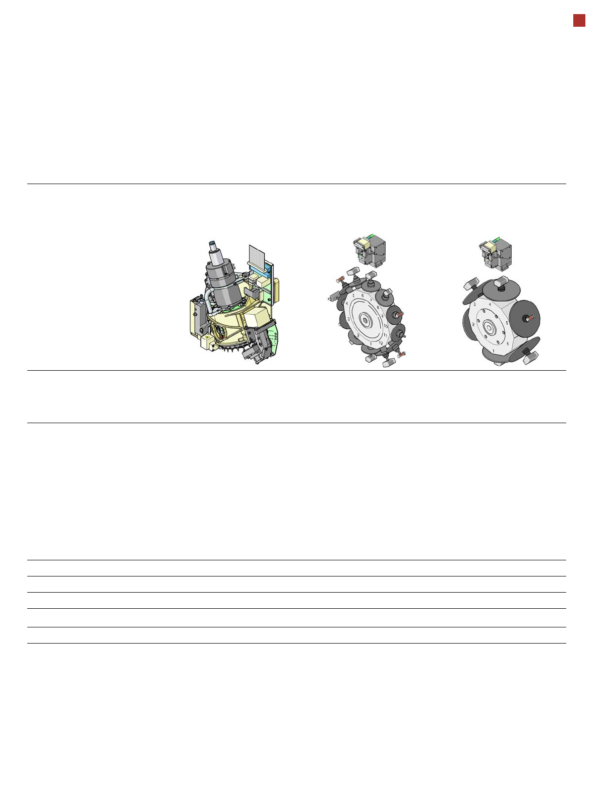
Technical Data for C&P Heads
20 segment
Collect&Place CA head
component camera type 41
12 segment
Collect&Place CA head
component camera type 29
6 segment
Collect&Place CA head
component camera type 29
Component range
a
a) Please note that the range of components that can be placed is also affected by the pad geometry, customer-specific standards,
component packaging tolerances and component tolerances.
01005 to 2220, Melf, SOT,
SOD, Bare-Die, Flip-Chip
0201
b
to Flip-Chip, Bare-
Die, PLCC44, BGA, µBGA,
TSOP, QFP, SO to SO32,
DRAM
b) with 0201 package;
0201 to 27 mm x 27 mm
Component spec.
max. height
min. lead pitch
min. lead width
min. ball pitch
min. ball diameter
min. dimensions
max. dimensions
max. weight
4 mm
0.08 mm
0.03 mm
0.10 mm
0.05 mm
0.12 mm x 0.12 mm
6 mm x 6 mm
1 g
6 mm
0.3 mm
0.15 mm
0.13 mm
0.08 mm
0.6 mm x 0.3 mm
18,7 mm x 18,7 mm
2 g
8.5 mm
0.3 mm
0.15 mm
0.13 mm
c
0.35 mm
d
0.08 mm
c
0.2 mm
d
0.6 mm x 0.3 mm
27 mm x 27 mm
5 g
c) for components < 18 mm x 18 mm;
d) for components 18 mm x 18 mm.
Programmable set-down force 1.5 N - 4.5 N 2.4 N - 5.0 N 2.4 N - 5.0 N
Nozzle types 10xx, 11xx, 12xx 9 xx 8 xx, 9 xx
X/Y accuracy (SMT) ± 41 µm/3 ± 41 µm/3 ± 45 µm/3
X/Y accuracy (CA)
e
e) Calculated with glass die on glass plate - SIPLACE MAC test
± 10 µm/3 ± 25 µm/3 ± 35 µm/3
Angular accuracy ± 0.5° / 3 ± 0.5° / 3 ± 0.2° / 3