Specification SIPLACE CA-Series2011版.pdf - 第44页
44 Technical data Siemens Signal Interface - Signal Sequence 1. After swit ching on t he statio n Transport direction Belt n Belt n+1 PCB sensor PCB sensor Station n transports PCB to the transfer position Belt n running…

43
Technical data
Siemens Signal Interface - Connector Assignment
Signal interface (14-pole connecting socket, interface standard 1.2)
Upstream station X1 Downstream station X2
Pin 1 NOT READY + Pin 1 NOT READY +
Pin 2 NOT READY – Pin 2 NOT READY –
Pin 3 BOARD AVAILABLE + Pin 3 BOARD AVAILABLE +
Pin 4 BOARD AVAILABLE – Pin 4 BOARD AVAILABLE –
Pin 5 Not used Pin 5 Not used
Pin 6 Not used Pin 6 Not used
Pin 7 Not used Pin 7 Not used
Pin 8 Reserved Pin 8 Reserved
Pin 9 Reserved Pin 9 Reserved
Pin 10 Reserved Pin 10 Reserved
Pin 11 Reserved Pin 11 Reserved
Pin 12 Reserved Pin 12 Reserved
Pin 13 Reserved Pin 13 Reserved
Pin 14 Reserved Pin 14 Reserved
44
Technical data
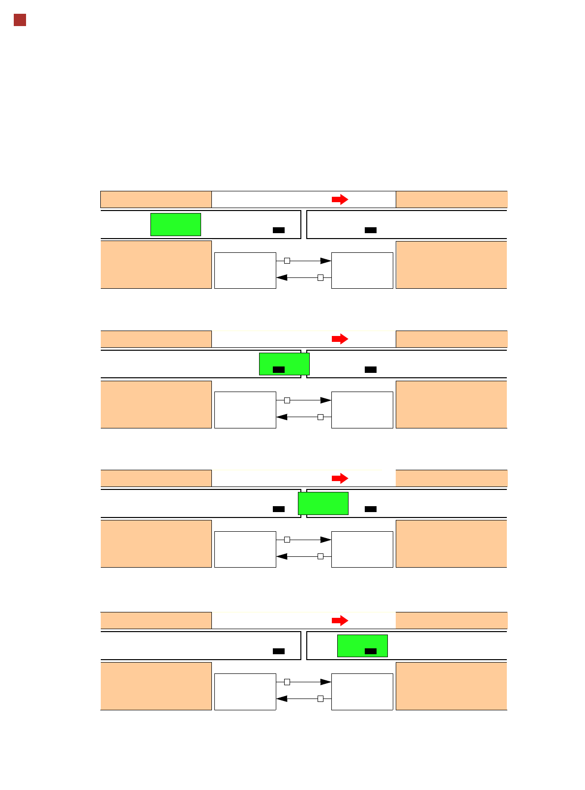
Siemens Signal Interface - Signal Sequence
1. After switching on the station
Transport direction
Belt n Belt n+1
PCB sensor PCB sensor
Station n transports PCB
to the transfer position
Belt n running Belt n+1 stopped
BOARD AVAIL-
ABLE
Permission
1
0
2. The PCB transfer has started
Transport direction
Belt n Belt n+1
PCB sensor
Station n transfers
PCB to Station n+1
Belt n running Belt n+1 running
Station n+1 expects
PCB from station n
3. PCB is transferred
Transport direction
Belt n Belt n+1
PCB sensor PCB sensor
Station n has
just transferred the PCB
Belt n stopped Belt n+1 running
Station n+1 expects PCB
from station n, but PCB
has not yet arrived.
PCB sensor
4. PCB transfer is complete
Transport direction
Belt n Belt n+1
PCB sensor PCB sensor
Station n
Belt n stopped Belt n+1 running
Station n+1
PCB arrived
Request
NOT READY
BOARD AVAIL-
ABLE
Permission
1
1
Request
NOT READY
BOARD AVAIL-
ABLE
Permission
0
1
Request
NOT READY
BOARD AVAIL-
ABLE
Permission
0
0
Request
NOT READY
To start a new PCB transfer, both signals must be "0" for at least 50 ms.
Station n+1
is not ready

45
Technical data
SMEMA Interface - Connector Assignment
Signal interface (14-pole connecting socket, interface standard 1.2)
Upstream station X1 Downstream station X2
Pin 1 NOT READY + Pin 1 NOT READY +
Pin 2 NOT READY – Pin 2 NOT READY –
Pin 3 BOARD AVAILABLE + Pin 3 BOARD AVAILABLE +
Pin 4 BOARD AVAILABLE – Pin 4 BOARD AVAILABLE –
Pin 5 Not used Pin 5 Not used
Pin 6 Not used Pin 6 Not used
Pin 7 Not used Pin 7 Not used
Pin 8 Reserved Pin 8 Reserved
Pin 9 Reserved Pin 9 Reserved
Pin 10 Reserved Pin 10 Reserved
Pin 11 Reserved Pin 11 Reserved
Pin 12 Reserved Pin 12 Reserved
Pin 13 Reserved Pin 13 Reserved
Pin 14 Reserved Pin 14 Reserved