Specification SIPLACE CA-Series2011版.pdf - 第7页
7 Machine Description SIPLACE Wafer System Description The SIPLACE W afer System (SWS) makes the compo- nents available to the place - ment head, directly from the wafer . The SWS therefore extends the component spectrum…

6
Machine Description
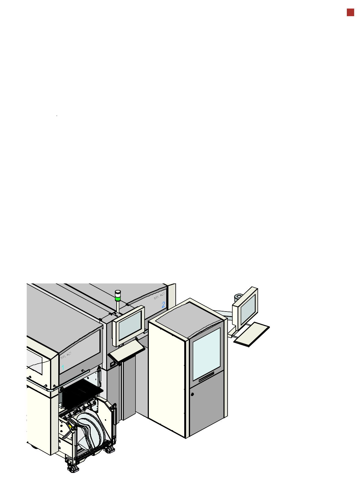
Overview
General
The "die attach" or "flip chip"
process enables the
SIPLACE CA (Chip Assem-
bly) platform to place bare
dies directly from the wafer.
This provides additional sup-
port for the SMT placement
options available with
SIPLACE X series ma-
chines. The SIPLACE CA
can be used either for bare
die or SMT placement alone
or for parallel placement of
both bare dies and SMT
components, in single pass
mode during the same pro-
cess. Users benefit from a
combination of greater pro-
cess flexibility and higher
placement speeds which is
unique to the electronics pro-
duction industry.
The placement machines in
the SIPLACE CA series are
available in two variants:
• SIPLACE CA3, the place-
ment machine with 3 gan-
tries and
• SIPLACE CA4, the place-
ment machine with 4 gan-
tries.
The SIPLACE CA4 can be
configured with up to 4 SWS
(S
IPLACE Wafer -System)
and the SIPLACE CA3 with
up to 2 SWS.
The SWS provides the place-
ment head with components
(dies) directly from the wafer
(max. 12“).
Placement machine
The placement machine
uses the Collect&Place-
method for high-speed
placement of standard com-
ponents.
The moving head picks the
components up from the
waiting SWS and places
them on the waiting printed
circuit board. This proven
SIPLACE principle has many
advantages:
• Short down times for refill-
ing or splicing
• Even the smallest compo-
nents are picked up reli-
ably
• The components cannot
slip on the PCB
• Minimal traversing paths
High flexibility, economic effi-
ciency and reliable setups
are the guarantee for the
high level of productivity in
the SIPLACE CA series
placement systems.
Minimum down times
increase utilization and thus
help to increase productivity.
Even small 01005 compo-
nents can be processed with
the SIPLACE CA series.
SIPLACE Wafer System
SWS
Integration of the SIPLACE
Wafer System (SWS) into
the SIPLACE CA facilitates
direct placement of dies from
the wafer, using a standard
SMT placement process.
This unique placement plat-
form supports both the "flip
chip" and "die attach" pro-
cesses.
• Processes supported:
Flip Chip, Die Attach (Chip
on Board), SMT
• Hoopring handling
• Horizontal wafer system
• Automatic wafer change
• Linear Dipping Unit
• Die Attach Unit
• ALPS wafer map software
• Multi die capability
7
Machine Description
SIPLACE Wafer System
Description
The SIPLACE Wafer System
(SWS) makes the compo-
nents available to the place-
ment head, directly from the
wafer. The SWS therefore
extends the component
spectrum of the established
SIPLACE X machines, by
enabling placement of bare
dies from wafers.
The wafers are supplied fully
automatically out of the wafer
cassette and the dies inside
can be processed in the
established placement pro-
cedures.
Flip chip process - func-
tion
The wafer is fully automati-
cally pulled out of the wafer
cassette and is then trans-
ported to the wafer table. The
wafer table positions the die
above the ejection system
that releases the die from the
wafer foil. After this release
procedure, the flip unit noz-
zle takes the die, rotates it by
180° and makes it available
to the placement head for
pickup.
Options
The process spectrum is
supplemented by the follow-
ing options:
– Die Attach Unit:
The die attach unit takes
the die from the flip unit
nozzle and turns it, so that
it has the same top-bottom
orientation on the board
as it had on the wafer.
– Linear Dipping Unit
The Linear Dipping Unit
distributes precise layers
of flux for the flip chip pro-
cess. After the dies have
been taken over from the
flip unit, the placement
head dips the dies into the
layer of flux.

8
Machine Description
Technical Data - SMT
Placement head
types
– 20 segment Collect&Place CA head (C&P20CA)
– 12 segment Collect&Place CA head (C&P12A)
– 6 segment Collect&Place CA head (C&P6)
– SIPLACE TwinHead (TH)
(only possible in a placement area without SWS).
Number of gan-
tries
CA4: 4 gantries
CA3: 3 gantries
Placement posi-
tion
6,000 / gantry for the Collect&Place heads
2,000 / gantry for the TwinHead
Component spec-
trum
a
a) The range of components depends on which head configuration is selected.
0.4 mm x 0.2 mm (01005), 0.6 mm x 0.3 mm (0201)
to 85 mm x 85 mm / 125 mm x 10 mm,
max. 200 mm x 125 mm (with restrictions)
Component
height
C&P20CA: 4 mm
C&P12: 6 mm
C&P6: 8.5 mm
TH: 25 mm
b
(higher heights on request)
b) The specified component height for TwinHead might be reduced in placement areas with two gantries and a combination
of Collect&Place head and TwinHead.
Placement accu-
racy
(Standard criteria
for SMD)
C&P20CA
C&P12
C&P6
TH
TH
± 41 µm (3), ± 55 µm (4)
± 41 µm (3), ± 55 µm (4)
± 45 µm (3), ± 60 µm (4)
± 26 µm (3), ± 35 µm (4)
± 22 µm (3), ± 30 µm (4)
Component camera, type 41 (6 x 6)
Component camera, type 29 (27 x 27)
Component camera, type 29 (27 x 27)
Component camera, type 33 (55 x 45)
Component camera, type 25 (16 x 16)
Placement accu-
racy
(Advanced crite-
ria for SWS)
C&P20CA
C&P12
C&P6
TH
TH
± 25 µm (3), ± 33 µm (4)
± 25 µm (3), ± 33 µm (4)
± 35 µm (3), ± 47 µm (4)
± 26 µm (3), ± 35 µm (4)
± 22 µm (3), ± 30 µm (4)
Component camera, type 41 (6 x 6)
Component camera, type 29 (27 x 27)
Component camera, type 29 (27 x 27)
Component camera, type 33 (55 x 45)
Component camera, type 25 (16 x 16)
Angular accuracy C&P20CA
C&P12
C&P6
TH
TH
± 0.5° (3), ± 0.7° (4)
± 0.5° (3), ± 0.7° (4)
± 0.2° (3), ± 0.3° (4)
± 0.05° (3), ± 0.07° (4)
± 0.05° (3), ± 0.07° (4
)
Component camera, type 41 (6 x 6)
Component camera, type 29 (27 x 27)
Component camera, type 29 (27 x 27)
Component camera, type 33 (55 x 45)
Component camera, type 25 (16 x 16)