Specification SIPLACE CA-Series2011版.pdf - 第26页
26 Placement heads Nozzle Changers Technical Data for the Nozzle Changers Configuration option s for nozzle changer Nozzle changer for the 20 segment Collect&Place CA head Dimensions (length x width x height) 449 x 9…
25
Placement heads
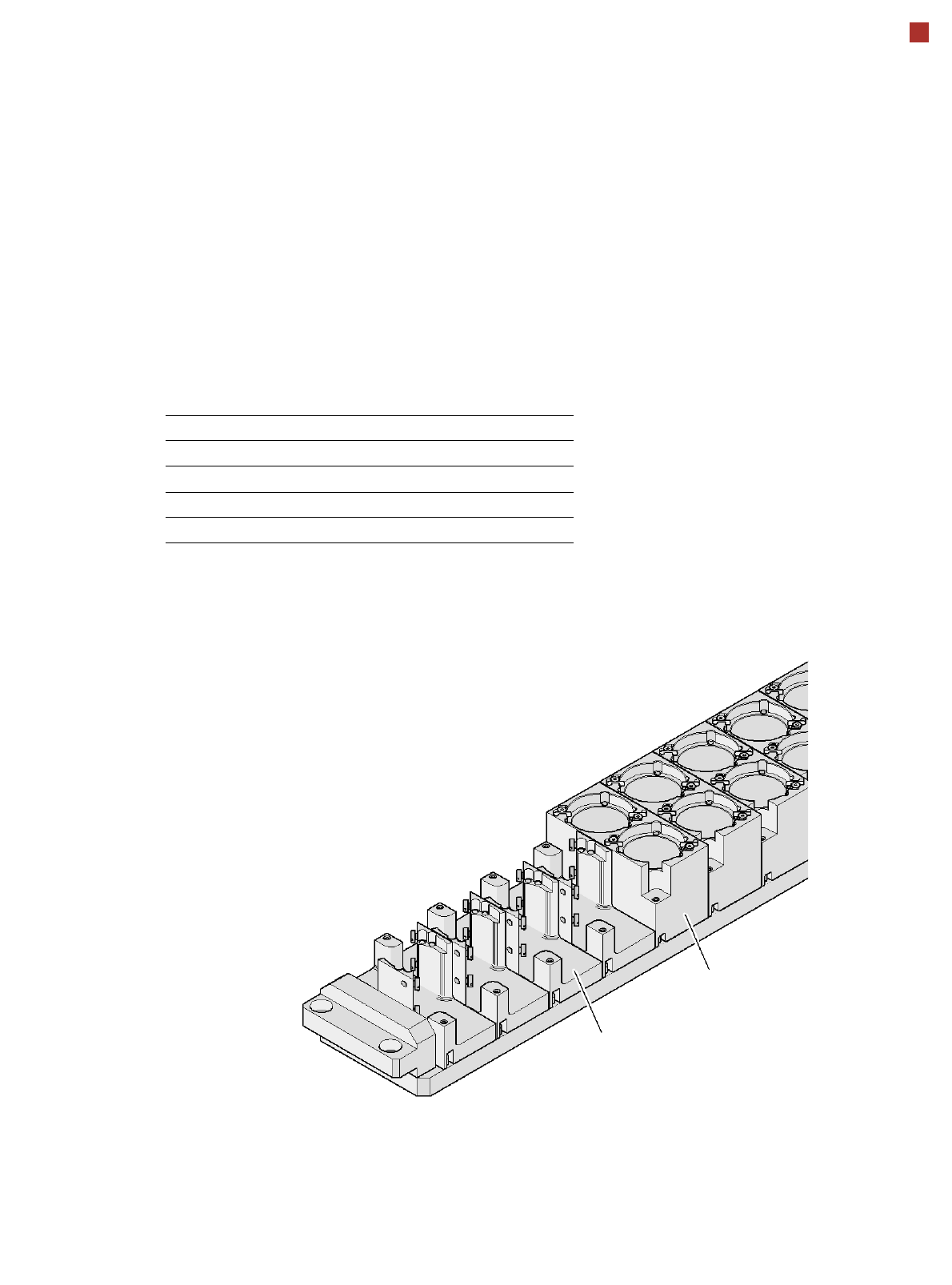
Nozzle Changer (TwinHead)
PLEASE NOTE:
A TwinHead can only be used in a placement area without SWS.
Magazine for two
standard nozzles
Magazine for one
special nozzle, gripper
The nozzle changer (NCTH) for the TwinHead (TH) can be installed for the
SIPLACE CA machines at the following locations:
The supporting plate can hold up to 12 magazines
for standard or special nozzles or grippers.
Location CA4
1 1 x NCTH
2 1 x NCTH
3 1 x NCTH
4 1 x NCTH

26
Placement heads
Nozzle Changers
Technical Data for the Nozzle Changers
Configuration options for nozzle changer
Nozzle changer for the 20 segment Collect&Place CA head
Dimensions (length x width x height) 449 x 94.5 x 79 mm³
Number of magazines 6, each with 12 nozzle holders
a
Number of nozzle holders 72
Nozzle types 10xx, 11xx, 12xx
Nozzle changeover time approx. 2 s
Compressed air connection 0.48 MPa (4.8 bar)
Nozzle changer for the 12 segment Collect&Place CA head
Dimensions (length x width x height) 449 x 62.7 x 77.7 mm³
Number of magazines min. 1 / max. 5, each with 12 nozzle holders
Nozzle types 9 xx
Nozzle changeover time approx. 2 s
Compressed air connection 0.48 MPa (4.8 bar)
Nozzle changer for the 6 segment Collect&Place CA head
Dimensions (length x width x height) 448 x 122.5 x 97.7 mm³
Number of magazines min. 1 / max. 6, each with 6 nozzle holders
Nozzle types 8 xx, 9 xx
Nozzle changeover time approx. 2 s
Compressed air connection 0.48 MPa (4.8 bar)
Nozzle changers for the SIPLACE TwinHead
Dimensions (length x width x height) 448 x 68.5 x 49 mm³
Number of magazines max. 12
Number of nozzle holders May be freely configured
Nozzle types 4 xx with adapter
5 xx (standard)
9 xx with adapter
Special nozzle, gripper
Nozzle changeover time approx. 2s per nozzle
a) All 6 magazines must always be set up.
The number of nozzle changers for the Collect & Place heads depends on the number of gantries
in the placement area:
- up to four nozzle changers may be installed in the placement area with two gantries
- up to three nozzle changers may be installed in the placement area with one gantry
If an SWS is used, CA systems are equipped with a nozzle changer at the relevant SWS loca-
tion. Depending on the placement head used a second bank can be configured.
27
PCB Conveyor
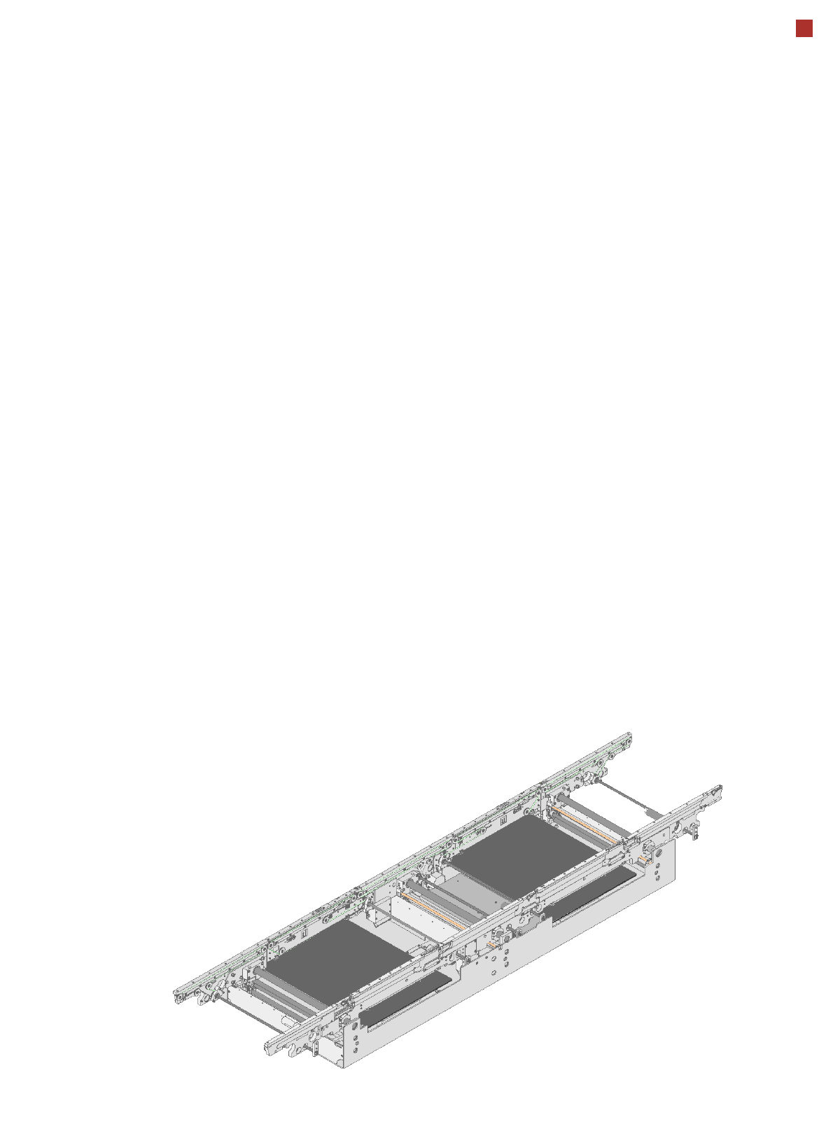
Single Conveyor
Description
For placement, the PCB is
clamped from below. The
distance between the top of
the PCB and the placement
head thus remains un-
changed for each PCB, and
is not dependent on the
thickness of the PCB. The
placement rate is thus inde-
pendent of the PCB thick-
ness.
Since the distance between
the PCB surface and the
PCB camera remains the
same, the PCB camera is al-
ways focussed on the PCB
surface with the same level
of sharpness.
The PCB fiducial contours
are optimally mapped on the
CCD chip of the PCB cam-
era.
The inline PCB conveyor
system quickly adapts to a
wide range of PCB widths.
The setting is made using the
placement program or via
the station software menu.
The width of the PCB con-
veyor is monitored by an in-
tegral control circuit.
The machine height can be
modified, thus allowing the
machines to be integrated
into lines with a transport
height of 830, 900, 930 or
950 mm.
-The communication be-
tween the PCB conveyors of
the individual machines is via
a SMEMA interface (optional
Siemens interface).
The fixed transport side can
be located on the left or right
for both the dual conveyor
and the single conveyor.
With this conveyor, the fixed
side can be easily switched
from right to left or vice versa.
Movement and clamping of
the PCBs are monitored. If
the board has reached the
placement area and passed
the light barrier, it is braked.
A laser light barrier deter-
mines the position of the
board. As soon as the board
has reached its target posi-
tion, the conveyor belt is
stopped and the board is
clamped from below. The
placement process then
starts immediately.
Placement area 1
Placement area 2
Output conveyor
Intermediate conveyor
Input conveyor