00198501-02_IM_711.1_R18-1_EN.pdf - 第62页
Station Software V ersion 711.1 (R 18 - 1) / Installat ion Manual 05/2018 Edition 62 7.3.1 SX1/SX2 (V2) Placement Machine ► When the SX1/SX 2 (V2) placement m achine is boote d for the first ti me you have to select the …
Station Software Version 711.1 (R18-1) / Installation Manual 05/2018 Edition
61
7.3 SX-Series Placement Machines
The System identification calibration feature has been introduced for the SX-series placement
machines in the automatic calibration. Therefore, an additional calibration step may be required
after installation. In this case, a warning is displayed that the calibration is not up to date. This also
applies for the respective station software version in compatible mode. Proceed as follows:
► Log in on the Machine service activity level.
► Switch to the Configure, update and calibrate machine menu.
► Press the Automatic calibration button.
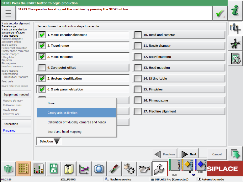
The following dialog box is displayed:
Figure 7-1: Calibration steps dialog box
► Select the System identification calibration step.
Or
► Select Selection – Gantry axes calibration.
All required calibrations will then be performed for the main axes and the machine provided
with the current data.

Station Software Version 711.1 (R18-1) / Installation Manual 05/2018 Edition
62
7.3.1 SX1/SX2 (V2) Placement Machine
► When the SX1/SX2 (V2) placement machine is booted for the first time you have to select the
following options manually:
– Table configuration for both locations.
– If the manual tray Carrier SX is used, the insert frame with the fold-away tape guide
channel is required. For this, the 60 slots (outer position, fold-away tape duct) table
configuration has to be selected for each location concerned. Thus, the 27x27 reject bin
and the left reject channel on the location are excluded from the configuration.
CAUTION
If this setting is not made, the component may be rejected over the tray and the Z axis
may dash hard against the tray.
► If the Coplan computer has been installed, you will additionally have to confirm or reject the 3-D
Coplan sensor.
7.3.2 SX+ Placement Machine
If the SX+ placement machine is to be used without gantries, this has to be configured in the auto-
configuration after the machine has been booted.
► For this, select Ignore gantries at the processing area in the machine configuration dialog.
7.3.3 SX4 Placement Machine
► When the SX4 placement machine is booted for the first time you have to select the SX4
Flexible entry for Machine frame manually in the auto-configuration, if there are tables in outer
position in processing area 2, as this is not detected automatically via sensors.
Tables in outer position are used when stationary cameras are in use.
► Otherwise you select the SX4 High Speed entry.
7.4 DX-Series Placement Machines
► When the DX placement machines are booted for the first time you have to select the following
options manually:
– For C&P12 placement head: height position (altitude)
– Lamp indicators (two-colored or three-colored)
– Table position:
inner 60 tracks
outer 60 tracks
outer with 30 tracks + free location for tray or WPC
– Confirm/reject 3-D Coplan sensor
Station Software Version 711.1 (R18-1) / Installation Manual 05/2018 Edition
63
7.5 TX-Series (V1 and V2) Placement Machines
► When the TX placement machines are booted for the first time you have to select the following
options manually:
– If SIPLACE JTF-ML is used, select the X-Table, multi tray feeder support option for the
JTF-ML Table 40X on Location 1.
– If no reject plate has been installed, you have to disable this option explicitly.
7.6 Checking/Updating the Embedded Software
If the correct embedded SW versions are not available on the machine, the machine boot gets
interrupted.
► In this case, perform an embedded SW download.
► Start an overall reference run for the machine.
7.7 Storage Location of the Machine Files (Calibration Data etc.)
The machine-specific configuration, measurement and parameter data is stored in XML files under
C:\Sirio\Work\Individual. These XML files contain all calibration data.