SOM-1929-001_w.pdf - 第19页
16 Tg 1423 -ID-SO 5.6 "Servo Alarm" T ab 0606 - 001 5.6 "Servo Alarm" T ab • Sheet Layout When t he [Ser vo Ala rm] tab is pre ssed in the " RECALL" window (subme nu), the following tab shee…

15
Tg1423-ID-SO
5.5 "Adj Menu" Tab
0606-001
[5] [Cmpnt scraper (Z) Unit Inching] Button
Perform the inching operation so that the gap distance between the
component scraping plate and the nozzle is as close as the designated
distance in [3].
Repeat the confirmation and inching operation to adjust it, using a
thickness gauge.
(Input Range: -201 to 201 pulses, -0.500 to 0.500 mm)
Notice
The nozzle might hit the component scraping plate, so take the
greatest care in entering the value.
[6] Offset Writing in Offset data
The offset data calculated on the basis of the travel distance in the
inching operation in [5], is entered.
[7] [Rotary Turret Recoil Operation] Button
Performs the index zeroing after the component scraper has been
retreated to the origin.
Notice
When the nozzle is located upper to the component scraping
plate, always complete the adjustment after the index
escaping.
(In normal index zeroing, the nozzle might hit the component
scraping plate because the zeroing of the component scraping
plate is always performed in advance).
16
Tg1423-ID-SO
5.6 "Servo Alarm" Tab
0606-001
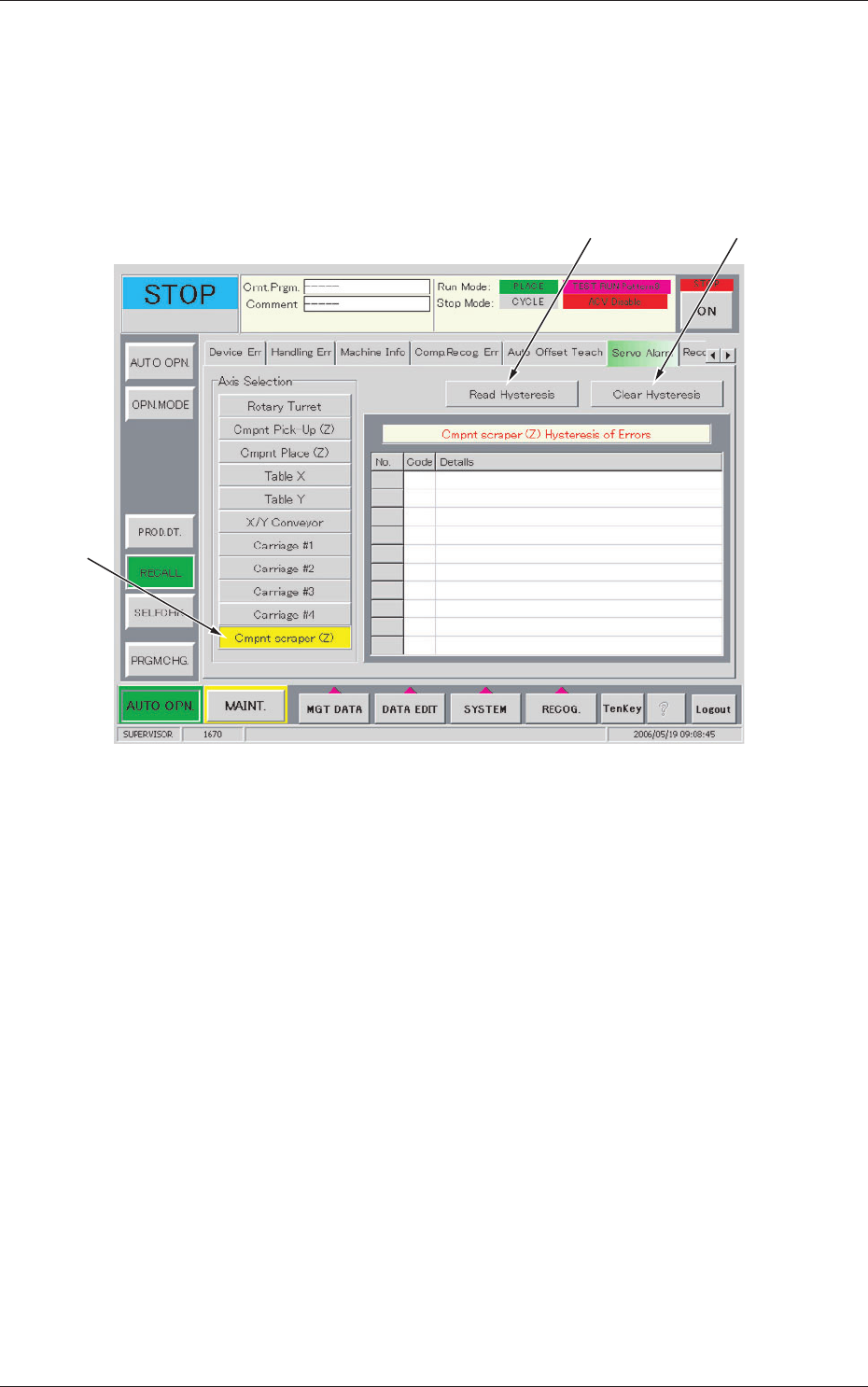
5.6 "Servo Alarm" Tab
•
Sheet Layout
When the [Servo Alarm] tab is pressed in the "RECALL" window (submenu),
the following tab sheet appears inside the window.
[1]
[2] [3]
Fig.9 "Servo Alarm" Tab Sheet
•
Sheet Composition
[1] Axis Selection (Alarm Type Selection)
[Cmpnt scraper (Z)] Button
Displays the "Cmpnt scraper (Z) Hysteresis of Errors".
[2] [Read Hysteresis] Button
When this button is pressed, the last 10 pieces of alarm data is displayed
with respect to the selected axis.
The data before the last 10 pieces is deleted.
[3] [Clear Hysteresis] Button
When this button is pressed, the alarm data of the selected axis is
cleared.
17
Tg1423-ID-SO
5.7"Device Offset" Tab
0606-001
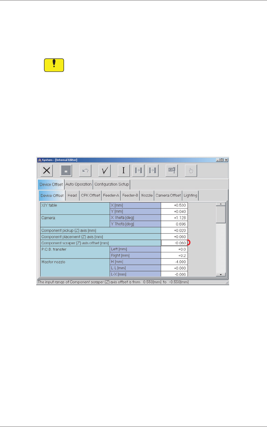
5.7 "Device Offset" Tab
This session describes how to set various kinds of offset data for each device
position adjustment related to machine operation, for the camera system
related to placement accuracy, for the heads, and for the nozzles.
Notice
Do not change the parameters unless necessary. These parameters
are factory-adjusted upon shipment of the machine.
Some parameters are automatically calculated through teaching
operations.
5.7.1 "Device Offset" Tab
•
Sheet Layout
When the [Device Offset] tab is pressed in the "Device Offset" tab sheet,
the following tab sheet appears.
[1]
Fig.10 "Device Offset" Tab Sheet
•
Sheet Composition
[1] Component scraper (Z) axis offset [mm]
Sets the offset for the component scraper.