SOM-1929-001_w.pdf - 第9页
6 Tg 1423 -ID-SO 4.2 Control Action and Description 0606 - 001 4.2 Control Action and Description (1) The position of the component scraping plate is moved up and down, based on the component thickness obtained from the …
5
Tg1423-ID-SO
3. Rough View
0606-001
3. Rough View
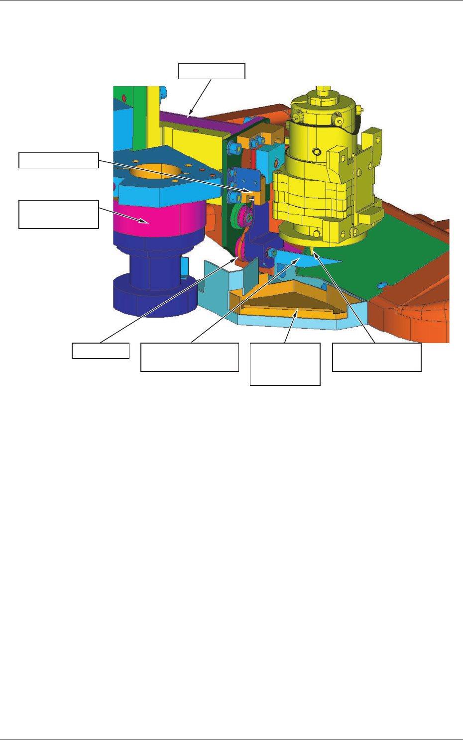
Photo Sensor
PEC Recognition
Camera
Driving Motor
Driving Belt
Component Scraping
Plate
Component
Discharging
Box
Nozzle for Fine
Components
Fig.1
4. Operation Procedure
4.1 Preparation and Setup
(1) The gap distance between the nozzle and the component scraping plate
can be changed by setting when it is applied to the fine components.
(2) The height of the component scraping plate can be adjusted by
measuring the gap distance between the nozzle and the scraping plate,
using a thickness gauge.
(3) When this system is used, perform the automatic teaching of the nozzle
level periodically.
(4) When this system is used, setup the component library as correct as
possible.
(5) For this system, periodical maintenance including oiling is not required.

6
Tg1423-ID-SO
4.2 Control Action and Description
0606-001
4.2 Control Action and Description
(1) The position of the component scraping plate is moved up and down,
based on the component thickness obtained from the Component
Library Data, under the following conditions.
When the nozzle level is set to "Low", the action of the component
scraping plate is based on the nozzle height resultant from the automatic
teaching, so the distance from the nozzle lower surface is changed in
its controlling the gap with the nozzle, depending on the component
thickness.
When the nozzle level is set to "High" (more than 2.5 mm of
Component Thickness), the position of the component scraping plate is
located at the uppermost position within the moving range, regardless
of the nozzle height.
Also the gap distance can be set to the following three stages.
(Initial Setting: Approach Level 2)
Also, depending on each Approach Level, the gap distance can be fine-
adjusted within the range of 1 to 100%.
For the range of 1 to 100%, that is decided on the basis of the value of
the upper level of the selected level (ex: Level 1 in the case of Level 2),
as 0%, and the values of 100% for each Approach Level are shown in
Table 2.
In the case of Level 1, the level adjustment rate is ineffective, so the
value can not be closer than the value in Table 2.
•
Component Thickness (T) and Gap Distance between the
Nozzle and Scraping Plate in Each Approach Level
(Level Adjustment Rate of 100%)
Table 2
Component Thickness
[mm]
Approach level 1 [mm] Approach level 2 [mm] Approach level 3 [mm]
0.10
<=
T
<=
0.20 0.05 0.06 0.08
0.20
<
T
<=
0.35 0.06 0.08 0.10
0.35
<
T
<=
0.50 0.08 0.10 0.15
0.50
<
T
<=
2.50 0.10 0.15 0.20
Reference
When the level adjustment rate is set to 100%, the gap distance for the
component with the thickness of 0.24 mm is as follows: as Approach Level
1 = 0.06 [mm] and Approach Level 2 = 0.08 [mm]
Gap Distance = Approach Distance of the Upper Level + (Difference from
the value in Upper Level)
×
70/100 = 0.06 + (0.08 - 0.06)
×
0.70 = 0.074
[mm]
7
Tg1423-ID-SO
4.2 Control Action and Description
0606-001
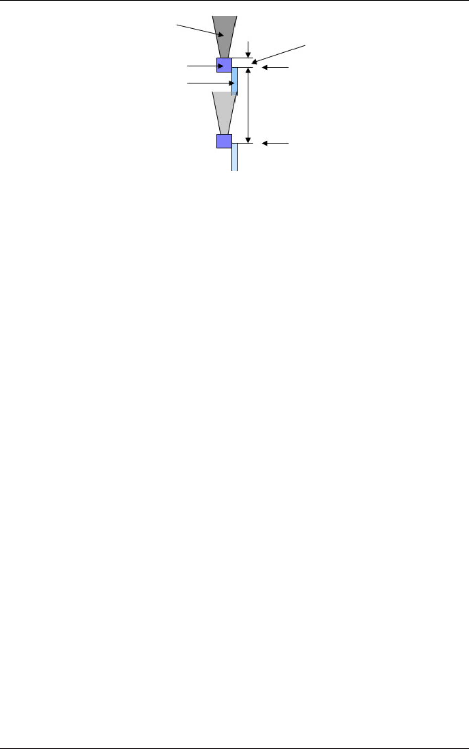
Component
Component Scraping Plate
(Depending on the vacuum
nozzle position, it moves up
and down keeping a certain
distance from the nozzle).
Gap between the Vacuum Nozzle
and Scraping Plate
Uppermost Position
Driving Range
(0.5 mm)
Origin Position
(Lowermost Position)
Vacuum Nozzle
(Position varies due to
Individual Di
fference)
Fig.2
4.3 Other Actions
(1) In the machine zeroing operation and stopping condition excluding
pause mode, the component scraping plate is located at the origin
position (lowermost position).
(2) In the start-up of the automatic operation of the machine, the warm-up
operation of the component scraping plate driving motor is performed
automatically.