SOM-1929-001_w.pdf - 第21页
18 Tg 1423 -ID-SO 5.8 "Auto Operation" T ab 0606 - 001 5.8 "Auto Operation" T ab 5.8.1 "Auto Operation Setup" T ab • Sheet Layout When the [Auto Operation Setup] tab is pressed in the "…
17
Tg1423-ID-SO
5.7"Device Offset" Tab
0606-001
5.7 "Device Offset" Tab
This session describes how to set various kinds of offset data for each device
position adjustment related to machine operation, for the camera system
related to placement accuracy, for the heads, and for the nozzles.
Notice
Do not change the parameters unless necessary. These parameters
are factory-adjusted upon shipment of the machine.
Some parameters are automatically calculated through teaching
operations.
5.7.1 "Device Offset" Tab
•
Sheet Layout
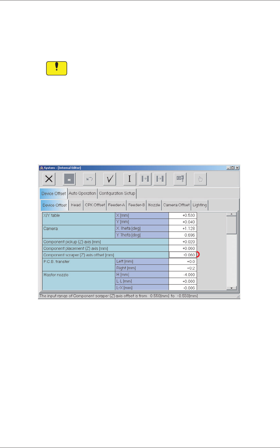
When the [Device Offset] tab is pressed in the "Device Offset" tab sheet,
the following tab sheet appears.
[1]
Fig.10 "Device Offset" Tab Sheet
•
Sheet Composition
[1] Component scraper (Z) axis offset [mm]
Sets the offset for the component scraper.
18
Tg1423-ID-SO
5.8 "Auto Operation" Tab
0606-001
5.8 "Auto Operation" Tab
5.8.1 "Auto Operation Setup" Tab
•
Sheet Layout
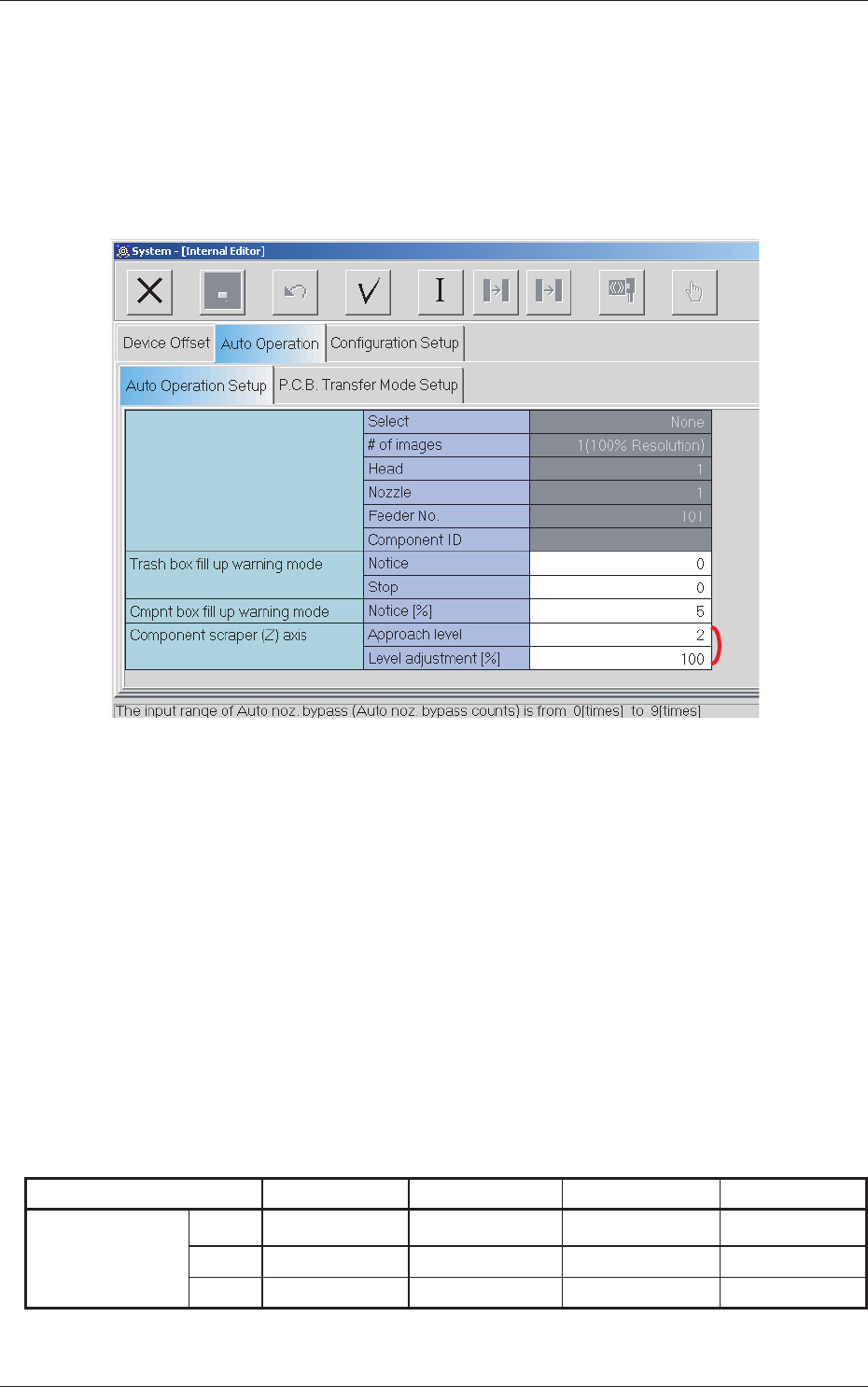
When the [Auto Operation Setup] tab is pressed in the "Auto Operation" tab
sheet, the following tab sheet appears.
[1]
Fig.11 "Auto Operation Setup" Tab Sheet
•
Sheet Composition
[1] Component scraper (Z) axis
Approach level
Enables the setting of the approach level (1 to 3) for the component
scraper.
Level sdjustment [%]
Enables the setting of the level adjustment rate (1 to 100) for the
component scraper.
During automatic operation, the approach distance between the nozzle and
the component scraper is decided on the basis of the following table.
Table 3
Component Thickness 0.00 to 0.20 0.20 to 0.35 0.35 to 0.50 0.50 to 2.50
Approach Level
Lv.1
0.05 0.06 0.08 0.10
Lv.2
0.06 0.08 0.10 0.15
Lv.3
0.08 0.10 0.15 0.20
Unit : [mm]

19
Tg1423-ID-SO
5.8 "Auto Operation" Tab
0606-001
Approach Distance = Approach Distance for the Upper Level + (Difference
from the value in the Upper Level)
×
(Level Adjustment / 100)
Reference
In the case of the Approach Level: Lv.2, Level Adjustment: 70%, and
Component Thickness: 0.24 [mm], the Approach Distance would be as
follows : 0.06 + (0.08 - 0.06)
×
0.70 = 0.074 [mm]