m220_383_02_process_manual工艺手册.pdf.pdf - 第11页
INTRODUCTION P ROCESS M ANU AL 1.Introduction 1.1 General The horizontal furnaces of Tem press Systems In c. are devel oped according to th e latest European directives for Machinery ( 98/37/EC) , Low Voltage ( 73/23/EC …

PREFACE
P
ROCESS MANUAL
V
III
Contents description
This manual is divided into the following sections and appendices:
Section 1 Introduction
Provides an overview of the Tempress Systems Inc.
Horizontal furnace, what it is and what it can do.
Section 2 Safety
Describes the safety components and functions. It describes all measures
that are required to provide a safe way of working.
Section 3 Process setup and acceptance
Describes the basis of how to setup a process recipe and how to handle
alarms that are generated during the process. Finally all minimal process
requirements for acceptable process results are defined in process
acceptance.
Section 4 Process description
Contains specific process information including chemicals used, start-up
parameters and a basic recipe layout.
Section 5 Operation Instruction
Describes all procedures that are required for the process engineer.
Revision History
This manual is revision 0 of the Process Manual and is intended to explain the required
procedures. The function and screens it describes are based on the following software
releases:
• TSC 2 version 6.0 (17-02-2003)
• DPC 2.I.03 (17-02-2003)
• DTC 2.F.02 (17-02-2003)
• Touchscreen 2.I.05 (17-02-2003)
For minor software and hardware changes, addendum to this manual will be available. For
major changes, a new revision will be available. For price information or other questions
please contact Tempress Systems Inc.
INTRODUCTION
P
ROCESS MANUAL
1.Introduction
1.1 General
The horizontal furnaces of Tempress Systems Inc. are developed according to the latest
European directives for Machinery (
98/37/EC), Low Voltage (73/23/EC) and EMC
(
89/336/EEC).
The Tempress Diffusion system is a modular horizontal furnace designed to process (silicon)
wafers as part of the manufacturing technology of semiconductor, optical, MEMS and solar
devices.
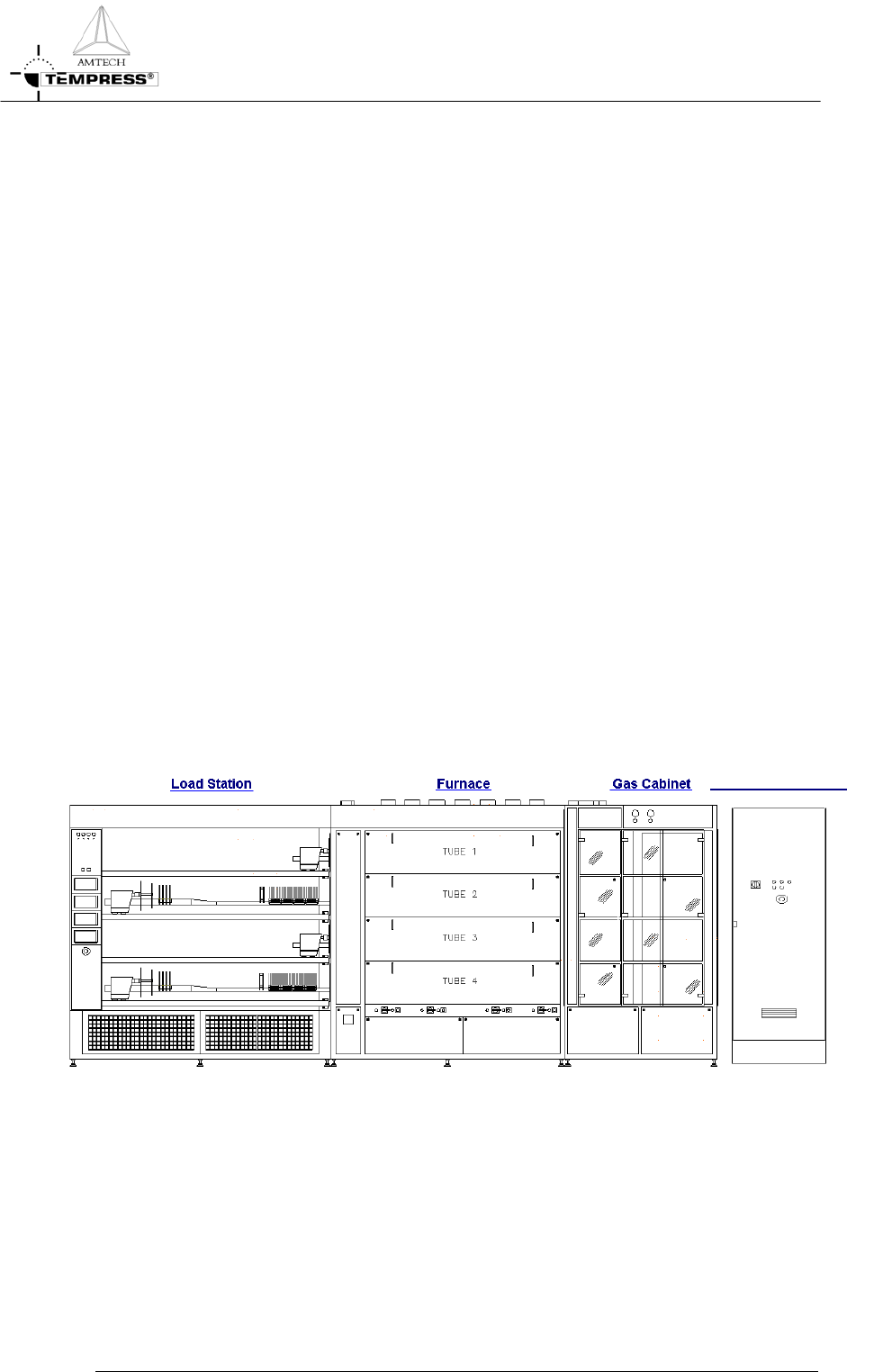
Figure 1-1 shows an example of a L-shape diffusion system with 4 process tubes shown
without the partition of a cleanroom wall.
It is a right-handed system, defined according to the position of the furnace relative to an
operator.
Usually the system contains more than 1 tube. Based on the number and size of tubes, the
system is referred to as a 2, 3 or 4 stack.
Figure 1-1 is an example of a 4-stack system, allowing up to 4 different processes at any time.
The tubes are numbered from 1 to 4, with tube number 1 at the top and tube 4 at the
bottom. All tubes operate fully independently.
Main Power Cabinet
Figure 1-1 Schematic view of a right-handed 4-stack Diffusion System
1-1
INTRODUCTION
P
ROCESS MANUAL
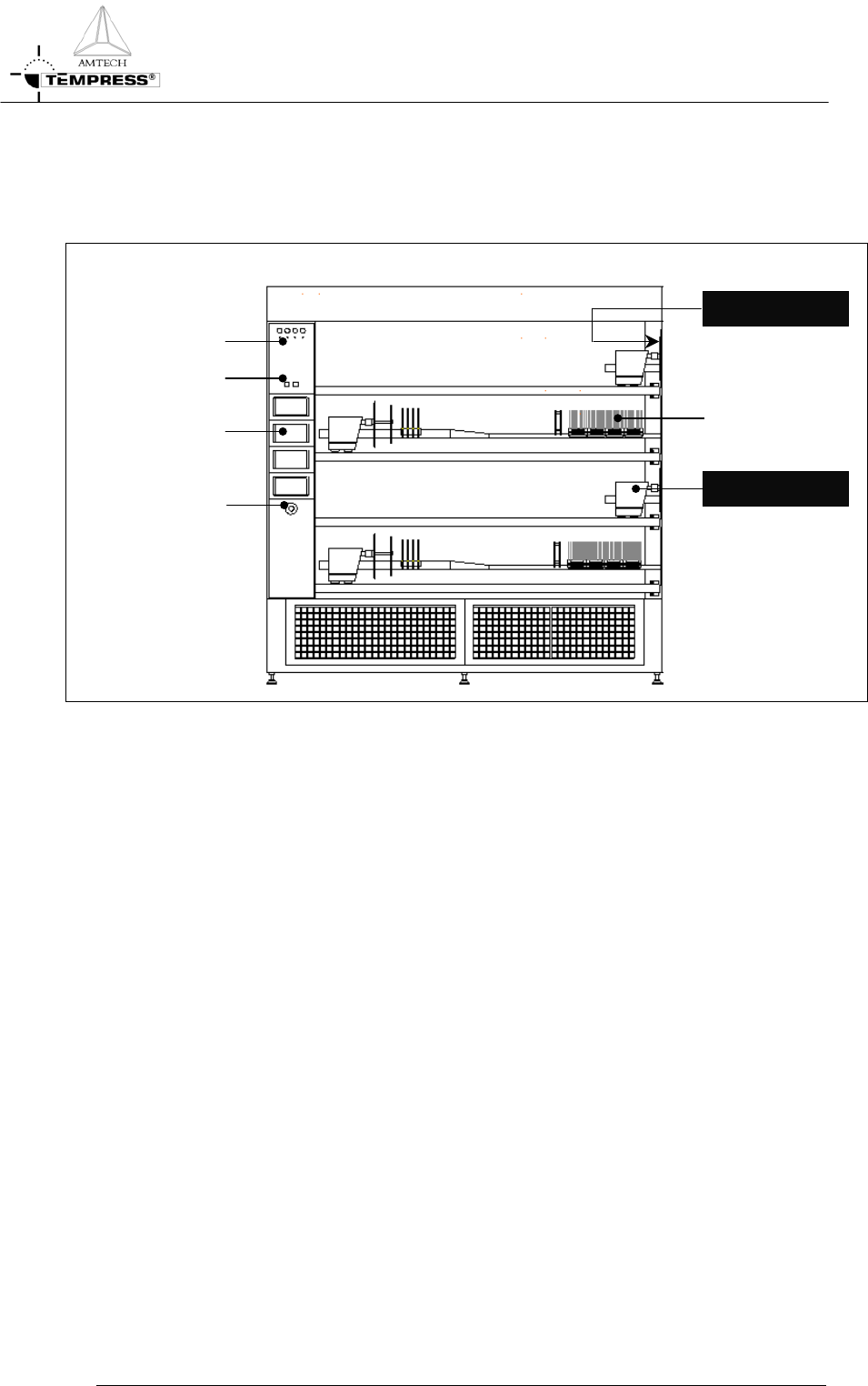
1.2 Process engineer area description
H S OT URFACE
1-2
Figure 1-2 Loadstation
The process engineer area is limited to the loadstation only. Figure 1-2 shows all relevant
items.
The Loadstation part of a Tempress System should be placed in the cleanroom. The Furnace
and Gas cabinet can optionally be placed in the greyroom.
To load wafers, several loader types can be implemented, including the (default) inline loader,
the Amtech Atmoscan
®
and the backmounted softlander. To prevent particles on the wafers
during the loading process, a constant horizontal laminar flow is created from the loadstation
into the cleanroom.
The loadstation is powered by 230V and has an illuminated On/Off switch for the fans and
the lights.
The remote control cabinet in the loadstation contains TFT-Touchscreens, one for each
tube. These are the user interface for communication with the Digital System Controllers
(DPC, DTC and DMC).
MOVING PART
W
afers
Buzzer
/
LED
T
ouchscreen
Light/Fan Switch