m220_383_02_process_manual工艺手册.pdf.pdf - 第16页
SAFETY P ROCESS M ANU AL 2-5 2.4 Toxic Material The process engineer, responsible for all process related activiti es, has to inform t he operator about the hazards of the process. See sec tion 4 Process description or s…
SAFETY
P
ROCESS MANUAL
2-4
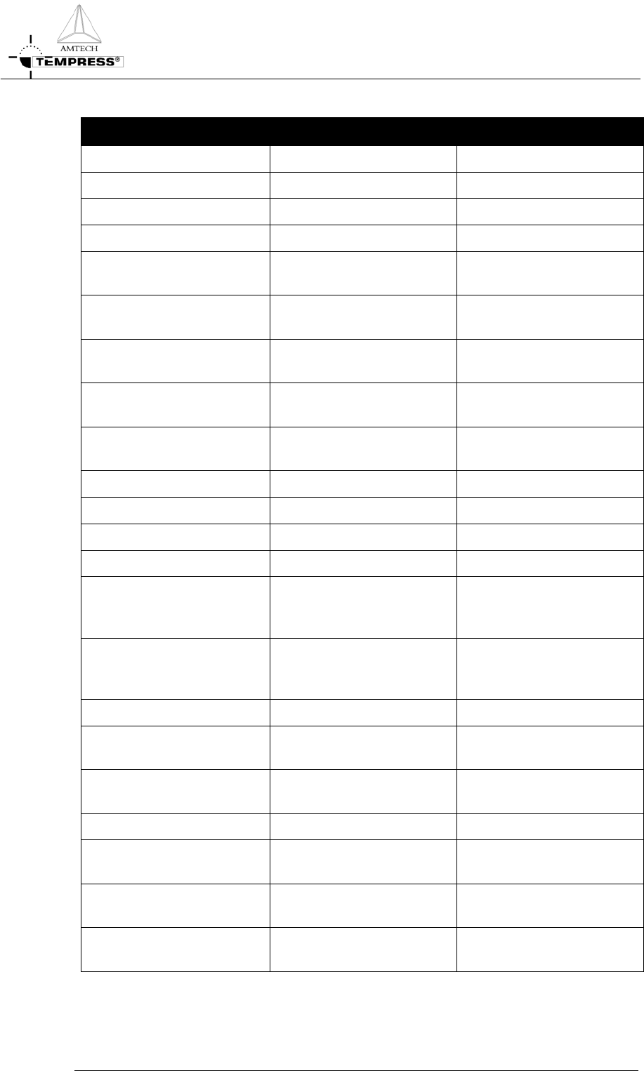
For a functional description of the light tower signals see table 1:
Signal Mode Description
Green ON Operational No warnings or messages
OFF Not operational
Yellow BLINKING N
2
pressure-switch No N
2
gas flow detected
Air pressure switch No Air flow detected
Torch temp (750) The torch temperature has
to exceed 750
o
C
Torch Flame failure There is no flame, the H
2
valve will be closed
Torch H
2
/O
2
ratio The H
2
/O
2
ratio exceeds
the safety value
Torch shell The skin temperature of the
torch is too high
Temperature sensor
powerpack
Temperature powerpack is
too high
Bubbler temp Bubbler temp is too high
Bubbler level Fluid level is too low
O
2
- low O
2
flow is too low
Exhaust (Low/High) Exhaust flow out of limits
Limit alarm (only if
programmed in the process
recipe)
Actual value is out of limits
Wait for operator (only if
programmed in the process
recipe)
Operator action is required
to continue
Process is finished
Boat manual Servo driver is in manual
mode
Maintenance mode Maintenance mode is
activated
OFF No alarm and/or alert
Red BLINKING Excess temperature
controller has been activated
Tube is overheated
(Optional) Leakage detection A gas or water leak has been
detected
OFF No alarm and/or alert No actual dangerous or
hazardous situation
Table 1 Light tower signal description

SAFETY
P
ROCESS MANUAL
2-5
2.4 Toxic Material
The process engineer, responsible for all process related activities, has to inform the operator
about the hazards of the process. See section
4 Process description or safety manual for a
complete description of all details.
2.5 Safety measures
Safety measures are indicated in the appropriate procedures.

PROCESS SETUP AND ACCEPTANCE
P
ROCESS MANUAL
3. Process setup and acceptance
3.1 Process recipe setup procedure
3.1.1 Introduction
The Tempress Systems, Inc. process controller, DPC, has some unique features that enable the user
to program any kind of process recipe in any way possible.
A process recipe is made of steps, and within one step several commands can be programmed.
The DPC is designed to execute commands in one particular step simultaneously. The sequence of
commands is therefor not important (except for “Branch on” and “Abort on “ alarm commands).
It is recommended, though, to use a consequent sequence to improve readability for the user.
3.1.2
6 steps to a process recipe
3.1.2.1 Step 1: Determine the required process temperature
The first step is to define the required process temperatures. These include the Load/Unload
temperature and the Process temperature(s).
Settings that need to be determined are the setpoint, the slope, the Hi and Low limits and the type
of temperature control (spike or paddle).
3.1.2.2 Step 2: Program the temperatures
The temperatures must be programmed in the DTC memory either using a touchscreen or using
the TSC-2 computer(s).
Touchscreen
2. certifications menu
2. temperature menu
2. normal temperature table
TSC-2
Recipes menu
Normal temperature menu
3.1.2.3 Step 3: Make temperature schematic
From the selected temperatures a schematic can be made that typically has the following shape:
3.1-1