m220_383_02_process_manual工艺手册.pdf.pdf - 第38页
PROCESS DESCRIPTION P ROCESS M ANU AL 4.1-3 TS630x 100 150 30 250 1000 800 20 60 TS660x 100 150 30 250 1000 800 30 90 TS680x 100 150 30 250 1000 800 40 120 TS6100x 100 150 30 250 1000 800 50 150 TS840x 150 200 30 250 100…
PROCESS DESCRIPTION
P
ROCESS MANUAL
4.1.2.4 Typicalities
Due to the low vapor pressure condensation may occur at any cold spot in the supply line.
Condensation leads to droplets formation, which cause MFC blockage. Heat tracing the
supply line strongly depends on the customer situation. A long distance between the bottle
cabinet and tube necessitates heating. This includes the bottle and lines supplied by the
customer, and the lines in the gas cabinet up to the MFC.
On the other hand, a small distance may not require heating and simple insulation may be
sufficient. Therefore, insulation and heating of the supply lines needs to be addressed at each
location. If it is a necessity apply an increased temperature from bottle to tube.
Due to the lower pressure downstream the MFC heating is not required from the MFC to the
tube and insulation is sufficient.
As DCS reacts with NH
3
the residual product is NH
4
Cl. That must be trapped using a
coldtrap. These gasses should be cooled down with a shock, not with a gradual decrease.
A cooled flange is required to extent O-ring lifetime, due to the high temperature of 770-800-
830
o
C. Especially at unloading conditions, the door O-ring is likely to burn. Also, the balljoint
O-ring receives a lot of heat, especially at pumping down conditions.
However, a too cold flange will cause NH
4
Cl condensation, which shows as a white powder
deposit on the flange.
To improve cross-wafer uniformity in the first few wafers it is necessary to apply a set of
dummy wafers at the gas inlet side of the load. An extra boat might be necessary.
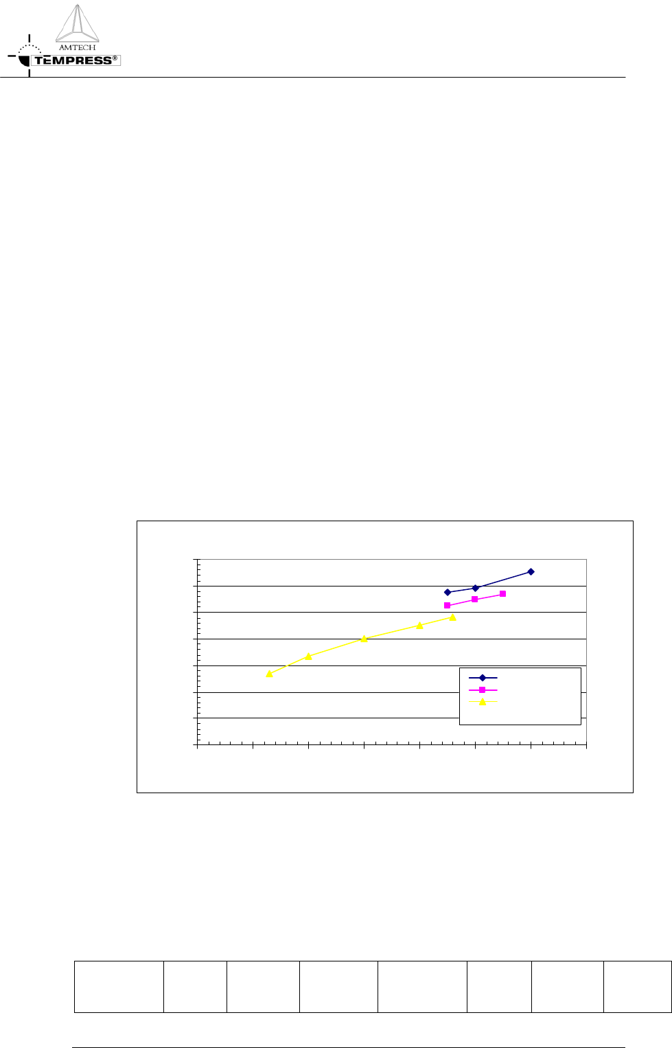
4.1.3
Process result indication
Nitride results (2)
pressure effect
0
10
20
30
40
50
60
70
0 50 100 150 200 250 300 350
deposition pressure [mtor]
thickness [A]
high flow
medium flow
low flow
4.1.4
Startup parameters for processing
The optical properties of a new and/or cleaned quartz tube change most dramatically after
the first deposition of foreign (=different refractive index) material. For accurate temperature
control a new and/or cleaned tube needs therefore to be coated before any (automatic)
profiling is performed. Use the default process settings for 1 hour to obtain a reasonable
coating.
Type Wafer
Size
[mm]
Process
Time
[min]
Pressure
[mtor]
Thickness
[Å]
Temp.
[
o
C]
SiH
2
Cl
2
[sccm]
NH
3
[sccm]
4.1-2

PROCESS DESCRIPTION
P
ROCESS MANUAL
4.1-3
TS630x 100
150
30 250 1000 800 20 60
TS660x 100
150
30 250 1000 800 30 90
TS680x 100
150
30 250 1000 800 40 120
TS6100x 100
150
30 250 1000 800 50 150
TS840x 150
200
30 250 1000 800 50 150
TS860x 150
200
30 250 1000 800 60 180
TS8100x 150
200
30 250 1000 800 100 300
TS1280x 200
300
30 200 1000 800 150 450
4.1.5
Recommended cleaning interval
Cleaning interval for the several components after cumulative deposition in microns on the
wafers.
Tube Cassettes /
baffles
SiC paddle Trap (upstream
tubing)
Oil and filter
change
Nitride 4 2 4 2 10
PROCESS DESCRIPTION
P
ROCESS MANUAL
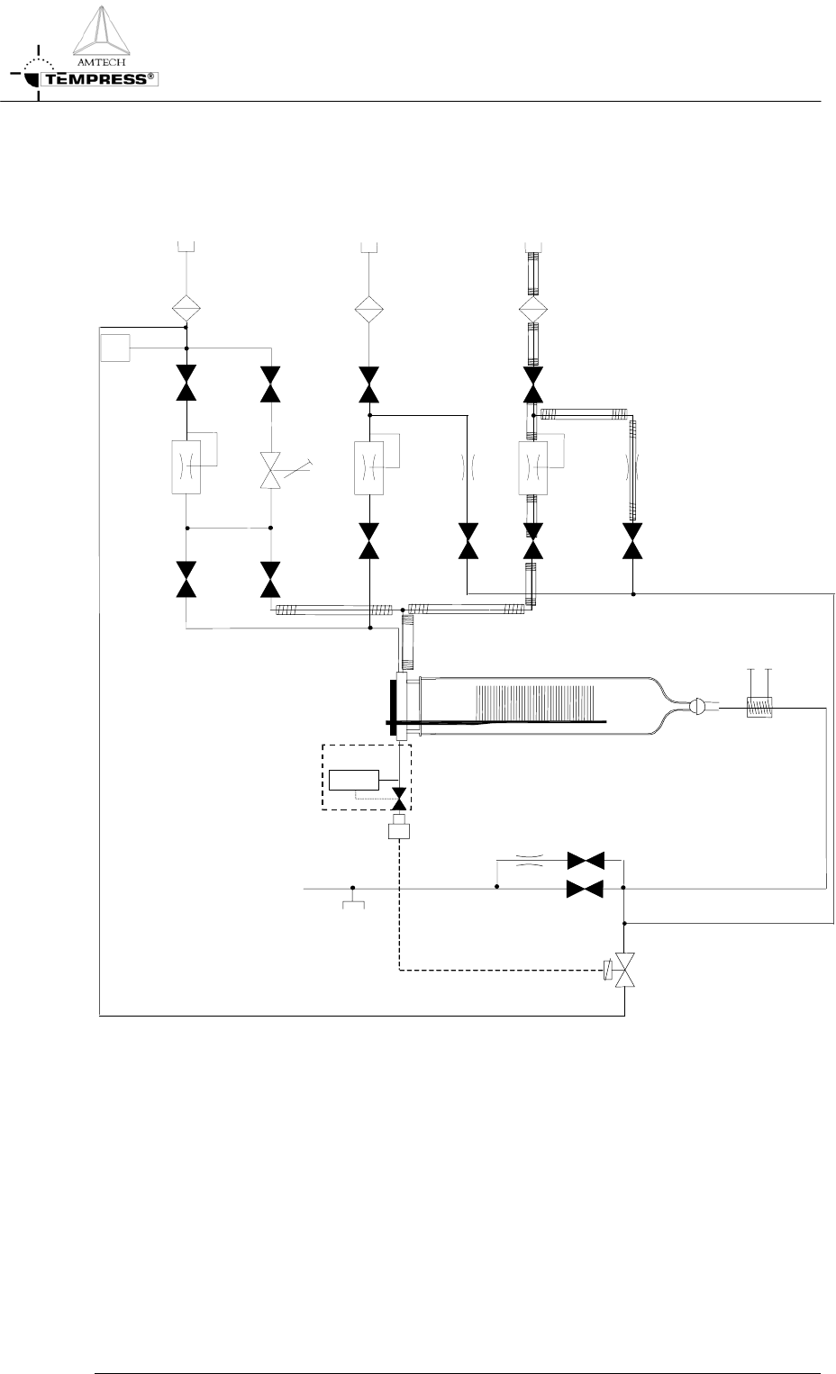
4.1.6
Gas schematic example: LPCVD siliconnitride
Water
Coldtrap
Baratron
10T/ATM
Vacuum
testport
To pump
PS
N
2
N
H
3
DCS
4.1-4