m220_383_02_process_manual工艺手册.pdf.pdf - 第25页
PROCESS SETUP AND ACCEPTANCE P ROCESS M ANU AL 3.3-4 17 Message ABO RTED !!! [16]. Sonalert alarm No 18 Time: 000:15:00 (hr:min:s ec) Variable Command: No 19 Digital out N2 PURGE[9] = ON,N2PROCE S[10] = ON,PROCESS[11] = …
PROCESS SETUP AND ACCEPTANCE
P
ROCESS MANUAL
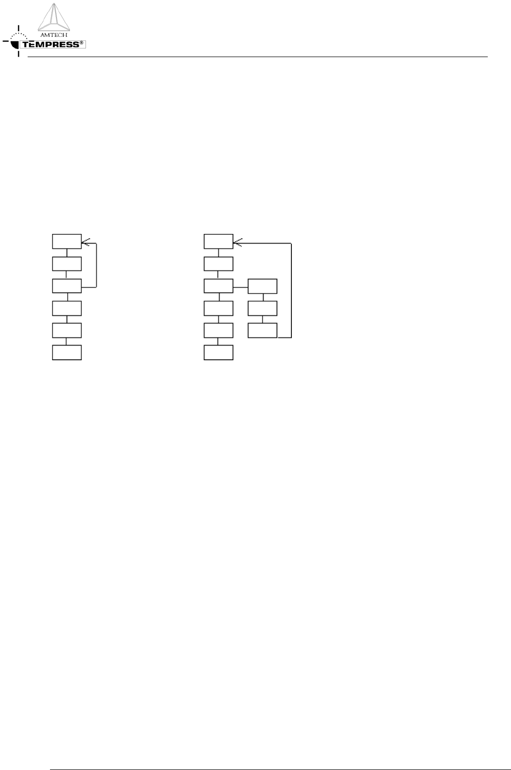
3.3.4.2 Manual abort command at any time
A manual Abort command can be issued at any time by an operator and should be used only if a potentially
dangerous or damaging situation is likely to occur that can only be prevented by aborting the running
process quickly.
Also, the manual Abort command is used to stop a process recipe with an endless loop.
Because the manual Abort command can be issued at any time, the use of an Abort recipe must be applied
as soon as in the process recipe potentially dangerous situations occur when that process recipe is aborted
and brought back to step 0.
Figure 3-3: An operator initiated Abort command without (left) and with (right) the use of an Abort recipe
3.3.5
Recipe example: LPCVD Nitride abort recipe
1 00 EVACUATE
2 Message ABORTED !!! [16]. Sonalert alarm No
3 Time: 000:15:00 (hr:min:sec) Variable Command: No
4 Normal recipe 00 Zone1 800.0 °C Slope 10.00 °C/min Zone2 800.0 °C Slope 10.00 °C/min
Zone3 800.0 °C Slope 10.00 °C/min Zone4 800.0 °C Slope 10.00 °C/min Zone5 800.0 °C Slope
10.00 °C/min , profile table A
5 Boat to 2000.0 mm at 300.0 mm/min with oscillation speed of 0.0 mm/min. Variable Command:
No
6 Gas N2 [1] at 0.00 [SLM ] Variable Command: No
7 Gas DCS 1 [2] at 0.0 [SCCM] Variable Command: No
8 Gas DCS 2 [3] at 0.0 [SCCM] Variable Command: No
9 Gas NH3 [4] at 0 [SCCM] Variable Command: No
10 Gas PRESSURE [8] at 0 [MTOR] Variable Command: No
11 Digital out ,,,,,,,WATERVLV[8] = ON Variable Command: No
12 Digital out N2 PURGE[9] = OFF,N2PROCES[10] = ON,PROCESS[11] =
ON,EVACDCS1[12] = OFF,EVACDCS2[13] = OFF,EVACNH3[14] = OFF,SOFTSTRT[15] =
ON,MAINVAC[16] = ON Variable Command: No
13 Alarm Limit Setting for All Analog Output Channel at 0 %
14 Alarm on digital in PRESS N2[1] = ON,PRESSAIR[2] = ON,DOORCLSD[3] =
ON,VACFAIL[4] = ON,WATRCOOL[5] = ON,,TEMP SCR[7] = ON,EXCESS[8] = ON
15 Alarm on digital in FANCONTR[9] = ON,,,OPERATE[12] = ON,WARNING[13] =
ON,FAILURE[14] = ON,,
16 01 PURGE
3.3-3

PROCESS SETUP AND ACCEPTANCE
P
ROCESS MANUAL
3.3-4
17 Message ABORTED !!! [16]. Sonalert alarm No
18 Time: 000:15:00 (hr:min:sec) Variable Command: No
19 Digital out N2 PURGE[9] = ON,N2PROCES[10] = ON,PROCESS[11] = ON,EVACDCS1[12]
= OFF,EVACDCS2[13] = OFF,EVACNH3[14] = OFF,SOFTSTRT[15] = ON,MAINVAC[16]
= ON Variable Command: No
20 02 EVACUATE
21 Message ABORTED !!! [16]. Sonalert alarm No
22 Time: 000:05:00 (hr:min:sec) Variable Command: No
23 Digital out N2 PURGE[9] = OFF,N2PROCES[10] = ON,PROCESS[11] =
ON,EVACDCS1[12] = OFF,EVACDCS2[13] = OFF,EVACNH3[14] = OFF,SOFTSTRT[15] =
ON,MAINVAC[16] = ON Variable Command: No
24 03 READY
25 Message STANDBY [1]. Sonalert alarm Yes
26 Digital out N2 PURGE[9] = ON,N2PROCES[10] = ON,PROCESS[11] = ON,EVACDCS1[12]
= OFF,EVACDCS2[13] = OFF,EVACNH3[14] = OFF,SOFTSTRT[15] = ON,MAINVAC[16]
= ON Variable Command: No
27 Wait for operator
28 04 BACKFILL 1
29 Message BACKFILL [14]. Sonalert alarm No
30 Time: 000:01:00 (hr:min:sec) Variable Command: No
31 Digital out N2 PURGE[9] = ON,N2PROCES[10] = ON,PROCESS[11] = ON,EVACDCS1[12]
= OFF,EVACDCS2[13] = OFF,EVACNH3[14] = OFF,SOFTSTRT[15] = ON,MAINVAC[16]
= OFF Variable Command: No
32 05 BACKFILL 2
33 Message BACKFILL [14]. Sonalert alarm No
34 Time: 000:10:00 (hr:min:sec) Variable Command: No
35 Gas N2 [1] at 10.00 [SLM ] Variable Command: No
36 Digital out N2 PURGE[9] = ON,N2PROCES[10] = ON,PROCESS[11] = ON,EVACDCS1[12]
= OFF,EVACDCS2[13] = OFF,EVACNH3[14] = OFF,SOFTSTRT[15] = OFF,MAINVAC[16]
= OFF Variable Command: No
37 END
PROCESS SETUP AND ACCEPTANCE
P
ROCESS MANUAL
3.4 Process acceptance conditions
The process specifications of Amtech/Tempress Systems, Inc. can only be guaranteed if the
conditions are satisfied as described in the following sections.
3.4.1
Introduction
The Tempress process is characterised with either film thickness, sheet resistivity, added particle
count, refractive index and/or dopant concentration, where applicable.
3.4.1.1 Uniformity definitions
Standard edge exclusion: 5 to 9 mm depending on wafer size and process unless otherwise stated in
the process specifications.
Table 3-2: Default edge exclusion
Wafer diameter
[mm]
Edge exclusion
[mm]
76.2 4
100 5
125 5
150 6
200 9
300 9
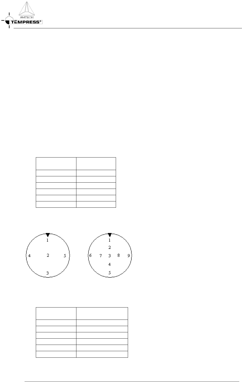
Minimum, maximum and average values are measured over 5 or 9 points as shown in the picture
below. Default amount of measurement points are indicated in
Table 3-3.
Figure 3-4: 5 or 9 measurement point indicator
Table 3-3: Default amount of measurement points
Wafer diameter
[mm]
Measurement points
[nr]
76.2 5
100 5
125 5
150 5
200 9
300 9
3.4-1