m220_383_02_process_manual工艺手册.pdf.pdf - 第36页
PROCESS DESCRIPTION P ROCESS M ANU AL 4.1-1 4.1 Nitride from NH 3 and SiH 2 Cl 2 4.1.1 Basic configuration NH 3 , SiH 2 Cl 2 (DCS) Temperature ramp at 700-800 o C 4.1.2 Description 4.1.2.1 Purpose Nitride is used as an i…

PROCESS DESCRIPTION
P
ROCESS MANUAL
4-1
4.Process description
A variety of guaranteed processes are available on the Tempress Diffusion systems, including:
Atmospheric
• Anneal
• Dry Oxidation (with or without TransLC
®
cleaning)
• Wet Oxidation (with or without TransLC
®
cleaning)
• POCl
3
Low pressure
• Ramped Poly
• Flat Poly
• Nitride
• TEOS
• LTO
• Ta
2
O
5
Because of the flexibility of the Tempress Systems Inc. systems variations on these processes are
available as well and will be manufactured on customer request.

PROCESS DESCRIPTION
P
ROCESS MANUAL
4.1-1
4.1 Nitride from NH
3
and SiH
2
Cl
2
4.1.1 Basic configuration
NH
3
, SiH
2
Cl
2
(DCS)
Temperature ramp at 700-800
o
C
4.1.2
Description
4.1.2.1 Purpose
Nitride is used as an insulating and masking layer in electrical applications, and as an anti-
reflecting coating in optical applications.
4.1.2.2 Chemicals
SiH
2
Cl
2
, also known as DCS (DiChloroSilane), is a liquid at room temperature with a vapor
pressure of 16 psi. Due to this relatively low vapor pressure it easily condensates at cold spots
and care should be taken to prevent these.
The residue of the reaction of DCS and NH
3
is NH
4
Cl.
Some properties of NH
4
Cl:
Sublimation at 320
o
C @ 1 atm.
Sublimation at 120
o
C @ 100 mtor. See also its vapor pressure curve in the appendix.
Two different forms are likely to occur:
A white powdery form and a glassy solid form. The glassy form is what occurs as the gasses
cool down abruptly on a cold surface. This is the form that is wanted on the coldtrap. The
white form occurs from condensation in the gas phase, and will not be trapped by the
coldtrap. Instead, it will be found at the inlet filter of the dry pump and in the exhaust of the
same pump, or in the oil of a wet pump.
4.1.2.3 Process
The chemical reaction is as follows assuming a complete reaction:
3SiH
2
Cl
2
+ 7NH
3
Æ Si
3
N
4
+ 6H
2
+ 3HCl + 3NH
4
Cl
The thickness uniformity decreases along the load due to depletion of DCS, much like
depletion of SiH
4
in the poly-Si process.
A temperature ramp as high as of + and – 30
o
C around the center temperature is sufficient to
overcome this problem. Cross-wafer uniformity is usually very good, since the deposition
process is limited by the surface reaction part. A decreasing process pressure does improve
the uniformity, mainly the cross load. If relatively small wafers are used compared to the tube
diameter an increased gas flow improves cross-wafer and cross-load uniformity dramatically.
PROCESS DESCRIPTION
P
ROCESS MANUAL
4.1.2.4 Typicalities
Due to the low vapor pressure condensation may occur at any cold spot in the supply line.
Condensation leads to droplets formation, which cause MFC blockage. Heat tracing the
supply line strongly depends on the customer situation. A long distance between the bottle
cabinet and tube necessitates heating. This includes the bottle and lines supplied by the
customer, and the lines in the gas cabinet up to the MFC.
On the other hand, a small distance may not require heating and simple insulation may be
sufficient. Therefore, insulation and heating of the supply lines needs to be addressed at each
location. If it is a necessity apply an increased temperature from bottle to tube.
Due to the lower pressure downstream the MFC heating is not required from the MFC to the
tube and insulation is sufficient.
As DCS reacts with NH
3
the residual product is NH
4
Cl. That must be trapped using a
coldtrap. These gasses should be cooled down with a shock, not with a gradual decrease.
A cooled flange is required to extent O-ring lifetime, due to the high temperature of 770-800-
830
o
C. Especially at unloading conditions, the door O-ring is likely to burn. Also, the balljoint
O-ring receives a lot of heat, especially at pumping down conditions.
However, a too cold flange will cause NH
4
Cl condensation, which shows as a white powder
deposit on the flange.
To improve cross-wafer uniformity in the first few wafers it is necessary to apply a set of
dummy wafers at the gas inlet side of the load. An extra boat might be necessary.
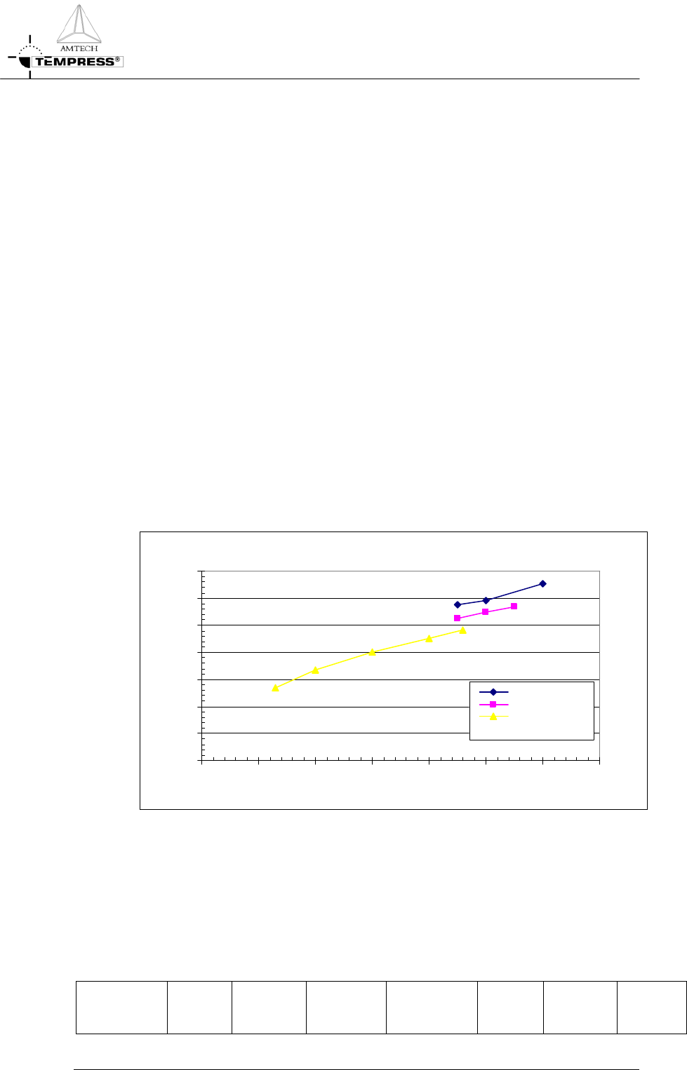
4.1.3
Process result indication
Nitride results (2)
pressure effect
0
10
20
30
40
50
60
70
0 50 100 150 200 250 300 350
deposition pressure [mtor]
thickness [A]
high flow
medium flow
low flow
4.1.4
Startup parameters for processing
The optical properties of a new and/or cleaned quartz tube change most dramatically after
the first deposition of foreign (=different refractive index) material. For accurate temperature
control a new and/or cleaned tube needs therefore to be coated before any (automatic)
profiling is performed. Use the default process settings for 1 hour to obtain a reasonable
coating.
Type Wafer
Size
[mm]
Process
Time
[min]
Pressure
[mtor]
Thickness
[Å]
Temp.
[
o
C]
SiH
2
Cl
2
[sccm]
NH
3
[sccm]
4.1-2