m220_383_02_process_manual工艺手册.pdf.pdf - 第18页
PROCESS SETUP AND ACCEPTANCE P ROCESS M ANU AL 3.1.2.4 Step 4: Make detailed schematic The schematic can be split into di fferent sections. E ach section is going to repres ent one process step. The detailed schematic ty…

PROCESS SETUP AND ACCEPTANCE
P
ROCESS MANUAL
3. Process setup and acceptance
3.1 Process recipe setup procedure
3.1.1 Introduction
The Tempress Systems, Inc. process controller, DPC, has some unique features that enable the user
to program any kind of process recipe in any way possible.
A process recipe is made of steps, and within one step several commands can be programmed.
The DPC is designed to execute commands in one particular step simultaneously. The sequence of
commands is therefor not important (except for “Branch on” and “Abort on “ alarm commands).
It is recommended, though, to use a consequent sequence to improve readability for the user.
3.1.2
6 steps to a process recipe
3.1.2.1 Step 1: Determine the required process temperature
The first step is to define the required process temperatures. These include the Load/Unload
temperature and the Process temperature(s).
Settings that need to be determined are the setpoint, the slope, the Hi and Low limits and the type
of temperature control (spike or paddle).
3.1.2.2 Step 2: Program the temperatures
The temperatures must be programmed in the DTC memory either using a touchscreen or using
the TSC-2 computer(s).
Touchscreen
2. certifications menu
2. temperature menu
2. normal temperature table
TSC-2
Recipes menu
Normal temperature menu
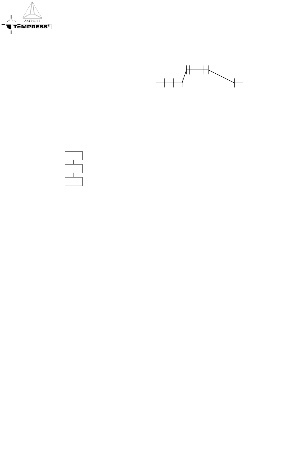
3.1.2.3 Step 3: Make temperature schematic
From the selected temperatures a schematic can be made that typically has the following shape:
3.1-1
PROCESS SETUP AND ACCEPTANCE
P
ROCESS MANUAL
3.1.2.4 Step 4: Make detailed schematic
The schematic can be split into different sections. Each section is going to represent one process
step. The detailed schematic typically has the following shape:
3.1.2.5 Step 5: Convert schematic to block diagram
The detailed schematic represents the individual steps that will be used in the process recipe. Each
step can also be presented in a block diagram with the following shape:
Step 0
Step 1
Step 2
3.1.2.6 Step 6: Fill in each block
Each block can now be programmed. It must be recognized that Step 0 (the first step) has some
unique properties that are not found in any other step:
1.'standby' step
2.selection of other recipe only here
3.must be started manually (no automatic continuation)
4.is the target for an Abort command
5.no time command available
6.no branch command available
7.no abort command available
3.1.3 Recommended command sequence
As stated previously, the DPC will execute all commands simultaneously, except for the
“Branch on” and “Abort on” instructions.
To improve readability the following sequence is recommended:
1.message
2.time
3.temperature
4.boat
3.1-2

PROCESS SETUP AND ACCEPTANCE
P
ROCESS MANUAL
3.1-3
5.analog out (MFCs)
6.digital out (valves)
7.alarm limits
8.alarm on digital inputs
9.branch on
10.abort on
11.wait for
12.abort recipe
As step 0 has been designed as the Standby step all commands in step 0 must be programmed
to create a safe condition.
This involves
closing
all
gas
flows and
valves
, except for a small N
2
purge flow, setting a
low temperature
and programming the
boat in
.
3.1.4
Modifying the default Tempress recipe
The default Tempress process recipe is designed with Step 0 as Standby for all atmospheric
processes. Obviously customers are free to alter the default recipe to fit their particular
needs. For example, a 24 hr production environment typically uses step 0 as Load/unload
step, not as a standby condition, because the machine is actually never in standby.
The transition is easy:
1) Modify the step 0 settings such that it contains:
1) Message Load/Unload with Sonalert
2) Boat out
3) Gas N
2
flow high
2) Remove step 1 Boat Out
3) Remove Step 2 Load Wafers