D4操作手册.pdf - 第11页
11 PCB Conveyor Single Conve yor Description For placem ent, the P CB is clamped from be low. The dis- tance b etween th e top of the PCB and t he placeme nt hea d thus remains unchanged for each PCB, an d is not dep en-…
10
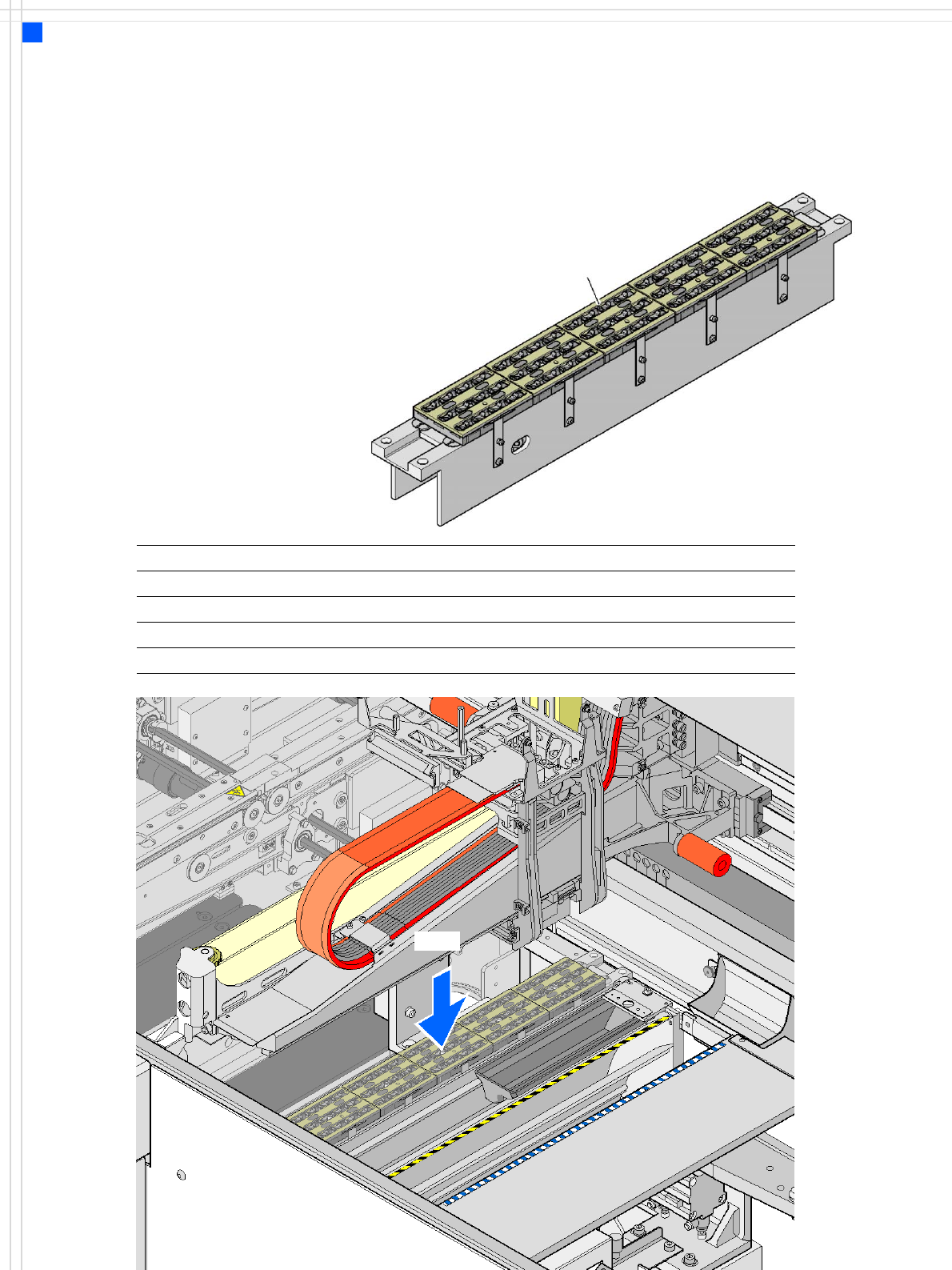
Nozzle Changers
Technical Data
Description
Nozzle changers increase the
flexibility of placement heads
when processing different
components. The nozzle con-
figuration can be quickly
modified for new placement
jobs. Exactly defined posi-
tions and the perfect seating
of the nozzle in the garage
guarantee minimal radial
eccentricity at the placement
head.
Technical data
Dimensions (length x width x height) 472.5 x 63 x 77 mm³
Number of magazines min. 1 / max. 5, each with 12 nozzle holders
Nozzle types 9 xx
Nozzle change time approx. 2s per nozzle
Compressed air connection 0.51 MPa ± 0.01 MPa (5.1 bar ± 0.1 bar)
Nozzle changer for the
12-nozzle Collect & Place head
(5 magazines → 60 nozzle holders in total)
Magazine for 12
type 9xx nozzles
NC12
11
PCB Conveyor
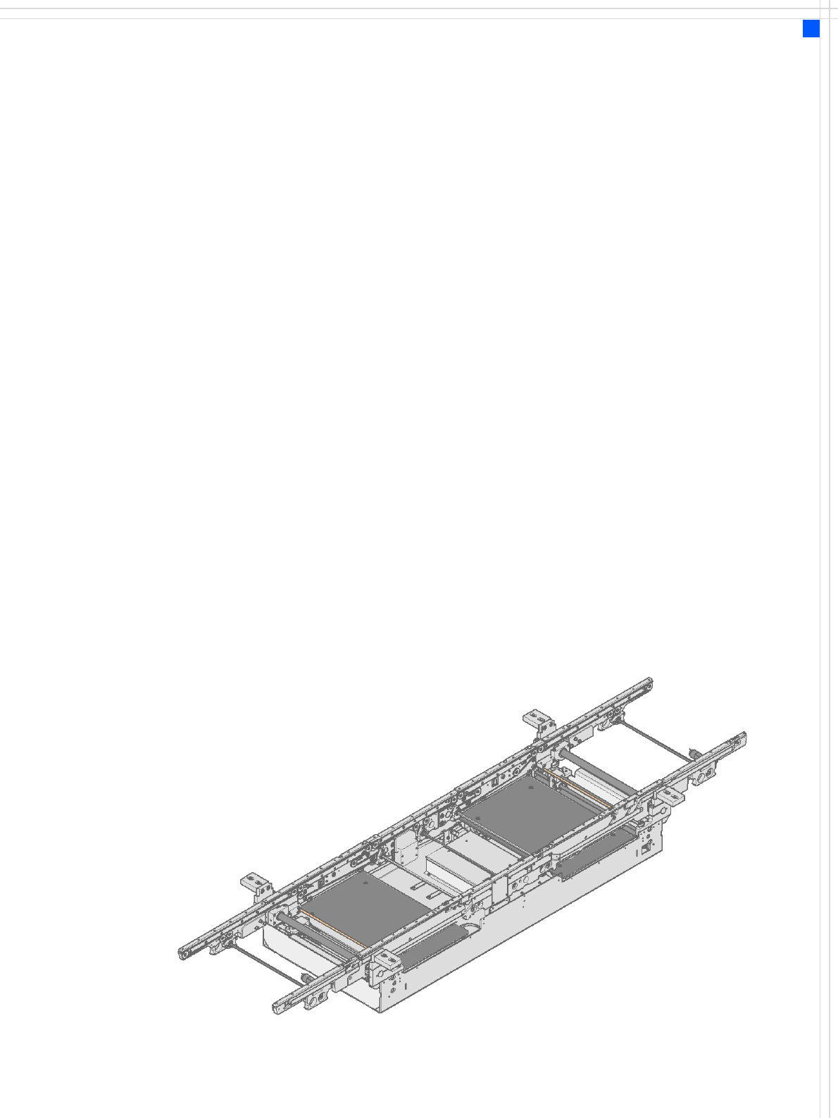
Single Conveyor
Description
For placement, the PCB is
clamped from below. The dis-
tance between the top of the
PCB and the placement head
thus remains unchanged for
each PCB, and is not depen-
dent on the thickness of the
PCB. The placement rate is
also independent of the PCB
thickness.
Since the distance between
the PCB surface and the PCB
camera remains the same,
the PCB camera is always
focussed on the PCB surface
with the same level of sharp-
ness.
The PCB fiducial contours
are optimally mapped on the
CCD chip of the PCB camera.
The inline PCB conveyor
system quickly adapts to a
wide range of PCB widths.
The setting is made using the
placement program or via
the station software menu.
The width of the PCB con-
veyor is monitored by an in-
tegral control circuit.
The machine height can be
modified, thus allowing the
machines to be integrated
into lines with a transport
height of 830, 900, 930 or
950 mm.
The PCB conveyors of the in-
dividual machines communi-
cate via the optional SMEMA
or Siemens interface.
The fixed transport side can
be located on the left or right
for both the dual conveyor
and the single conveyor.
With this conveyor, the fixed
side can be easily switched
from right to left or vice
versa.
Movement and clamping of
the PCBs are monitored.
When the board has reached
the placement area and
passed the light barrier, it is
braked. A laser light barrier
determines the position of
the board. As soon as the cir-
cuit board has reached its tar-
get position, the conveyor
belt is stopped and the board
is clamped from the under-
side. The placement process
then starts immediately.
Output conveyor
Intermediate conveyor
Input conveyor
Placement area 1
Placement area 2

12
PCB Conveyor
Single Conveyor
Technical Data
Fixed conveyor side Right or left
PCB format
Standard (length x width)
Wide board configuration
Long board option
Long board option in Wide board
configuration
50 x 50 mm² to 368 x 460 mm²
a
50 x 50 mm² to 368 x 508 mm²
a
50 x 110 mm² to 610 x 460 mm²
a
50 x 110 mm² to 610 x 508 mm²
a
PCB thickness
Standard 0.3 to 4.5 mm (± 0.2 mm)
(thicker PCBs on request)
Max. PCB warpage
(pass-through height)
up: 4.5 mm - PCB thickness
down: 0.5 mm + PCB thickness
PCB weight max. 3 kg
Clearance on PCB underside
Standard
Option
25 mm ± 0.2 mm
max. 40 mm ± 0.2 mm
Component-free PCB handling edge 3 mm
PCB changeover time 2.5 s
PCB positioning accuracy ± 0.5 mm
PCB transport height 830mm ± 15mm (standard)
900mm ± 15mm (optional)
930mm ± 15mm (optional)
950mm ± 15mm (SMEMA: optional)
Type of interface SIEMENS / SMEMA
b
Bad fiducial detection possible
Automatic width adjustment possible
a) With PCB widths > 450 mm make sure that the peripheral modules are also able to process these widths.
b) Option