D4操作手册.pdf - 第7页
7 Machine Description Technical Data Types of plac ement head 12-nozzle Collect & Place head (C&P12) Number of gantries 4 Placement rate a (Benchmark test) a) Accordin g to the definition in t he SIPLACE Scope of…
6
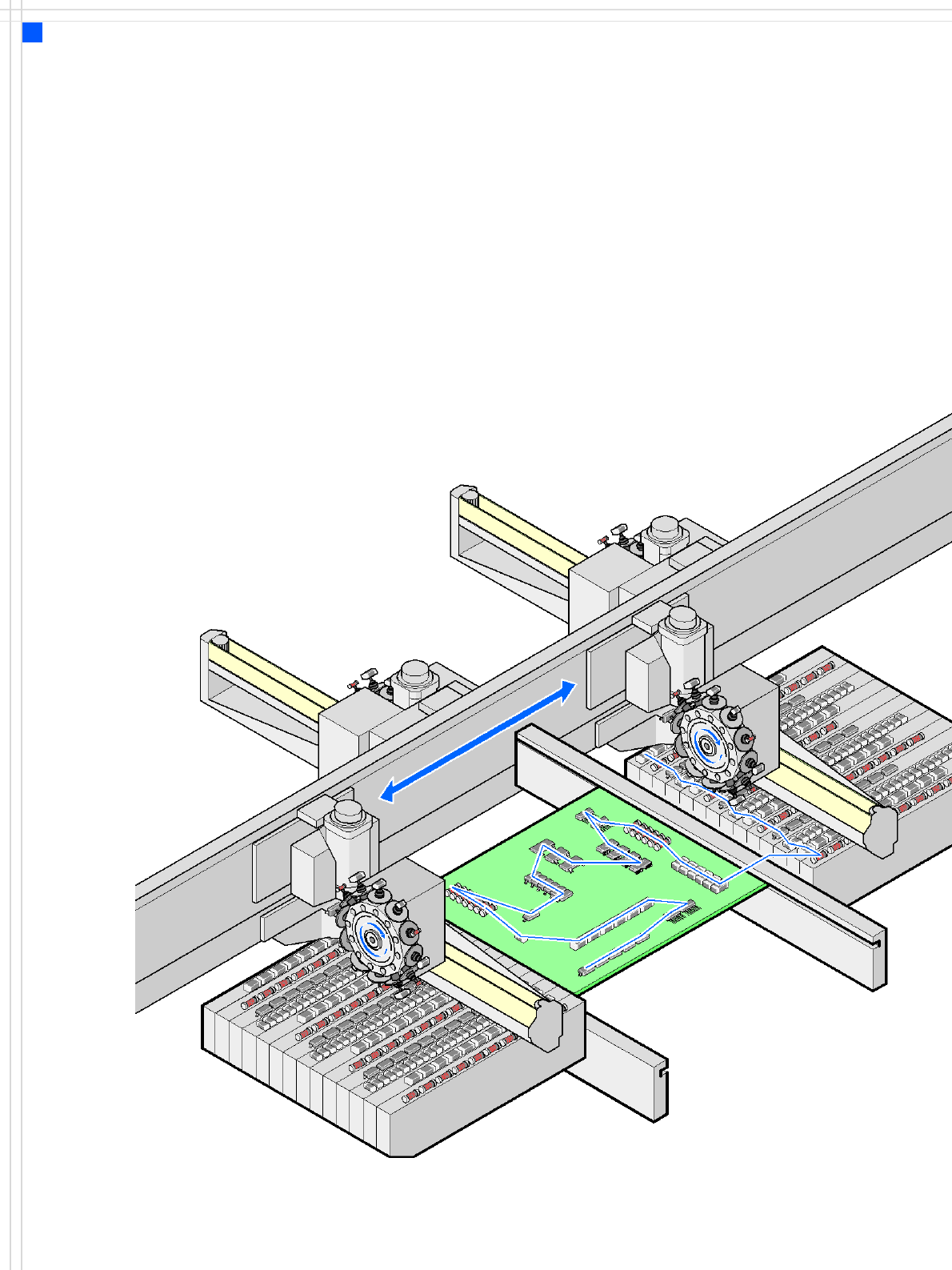
Placement principle
Collect & Place
Machine Description
Extensions
Extensions
The options available to ex-
tend the functionality of the
placement machine include
the following:
• Additional component
changeover tables in-
crease machine utilization
since set-up times can be
reduced by carrying out
preliminary set-up off the
machine.
• The flexible dual conveyor
also increases machine
utilization by eliminating
non-productive PCB trans-
port times.
• Automatic nozzle chang-
ers speed up and optimize
the nozzle configuration
process.
• PCB barcode scanners al-
low the production set-up
to be changed over when
triggered by a new
product.
• The productivity lift imple-
ments the concept of par-
allel placement, and thus
improves the ratio be-
tween productive and
non-productive times.

7
Machine Description
Technical Data
Types of placement head 12-nozzle Collect & Place head (C&P12)
Number of gantries 4
Placement rate
a
(Benchmark test)
a) According to the definition in the SIPLACE Scope of Service and Delivery
60,000 comp./h
Placement positions 6,000 / gantry
Range of components 0.4 x 0.2 mm² (01005)
b
, 0.6 x 0.3 mm² (0201)
c
to 18.7 x 18.7 mm²
b) 01005 optional, from April 2007
c) with 0201 package
Max. component height 6 mm
Placement accuracy / angular
accuracy
Camera type 28: ± 60 μm, ± 0.6° (3σ), ± 80 μm, ± 0.8° (4σ)
Camera type 29: ± 60 μm, ± 0.6° (3σ), ± 80 μm, ± 0.8° (4σ)
Component Feeding 4 component changeover tables with tape reel holders and
integral waste containers (12 locations, each 30 mm wide,
for each component changeover table)
Feeder module types Tapes, bulk cases, stick magazines, application-specific
OEM feeder modules, surftape feeder modules (8, 12,
16 mm)
Feeding capacity 48 tape feeder modules 3 x 8 mm S (144 tracks)
48 tape feeder modules 2 x 8 mm S (96 tracks)
48 tape feeder modules 12/16 mm S (48 tracks)
32 tape feeder modules 24/32 mm S (32 tracks)
PCB format
(LxW)
Single conveyor
50 x 50 mm² to 368 x 460 mm²
50 x 110 mm² to 610 x 460 mm² (Long board option)
(Width up to 508 mm available upon request)
Flexible dual conveyor
50 x 50 mm² to 368 x 216 mm²
50 x 110 mm² to 610 x 216 mm² (Long board option)
(Width up to 242 mm available upon request)
Flexible dual conveyor in Single conveyor mode
50 x 50 mm² to 368 x 380 mm²
50 x 110 mm² to 610 x 380 mm² (Long board option)
PCB thickness 0.3 - 4.5 mm (thicker PCBs on request)
Dimensions of the placement
systems
see page 30
8
Placement Head
12-Nozzle Collect & Place Head for High-
Speed Placement
Description
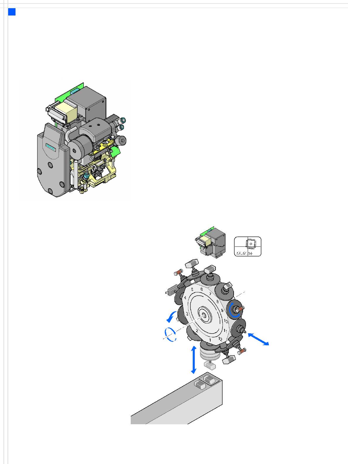
The 12-nozzle Collect & Place
head works on the Collect &
Place principle. This means
that, within each cycle,
twelve components are
picked up by the placement
head, are optically centered
on the way to the board and
are rotated into the required
placement angle. Lastly, the
air kiss sets down the compo-
nent gently and accurately
on the board.
Checking and self-learning
functions
The reliability of the Collect &
Place head is increased by
various checking and self-
learning functions.
• For example, vacuum
checks at the nozzles indi-
cate whether the compo-
nent was picked up
correctly.
•A digital component cam-
era on the placement head
determines the precise po-
sition of each component
at the nozzle. Any devia-
tions from the required
pick-up position are cor-
rected before placement
takes place.
• The package form is also
checked and the compo-
nent is not placed if the
geometric data thus deter-
mined differs from the
programmed data.
The vertical axis for picking
up and placing the compo-
nent works in sensor stop
mode, in which differences
in height during pick-up and
any unevenness of the PCB
surface are compensated
during placement.
In addition to the vacuum
check, an optional compo-
nent sensor may be used to
check for the presence of a
component at the nozzle.
The use of a component sen-
sor is recommended, particu-
larly when placing small
components, such as 0201.
High-resolution camera
option
The high-resolution compo-
nent camera allows the
12-nozzle Collect & Place
head to optically center and
place component sizes rang-
ing from 01005
1
, 0201 to
18.7 x 18.7 mm².
1) 01005 optional, from
April 2007
Component vision module
DP axis:
Rotate component
to placement angle
Pull off or
insert sleeve
Z axis
Pick up or
place component
DR axis:
Rotate star
Reject
component