D4操作手册.pdf - 第9页
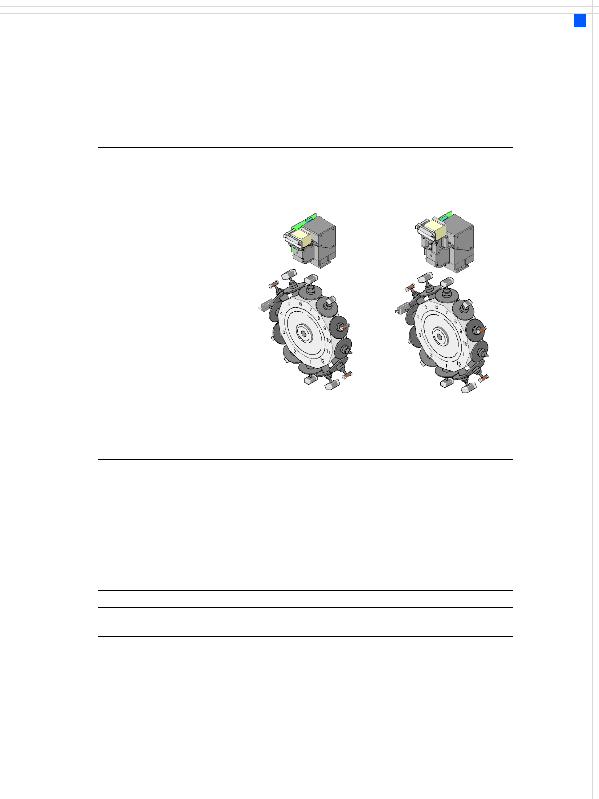
9 Placement Head Technical Data 12-nozzle Collect & Place head (standard - comp onent camer a) 12-nozzle Collect & Pl ace head (high-resolution com pone nt ca mera) Component r ange a a) Please note that the r an…
8
Placement Head
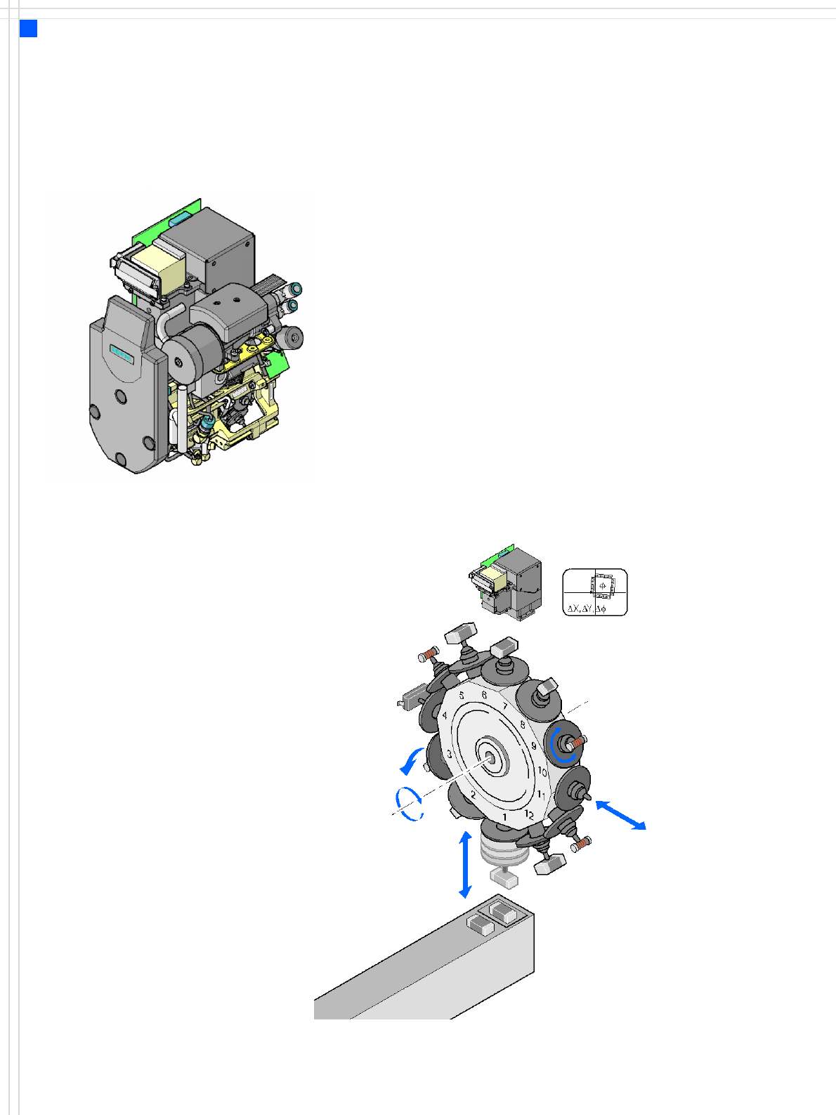
12-Nozzle Collect & Place Head for High-
Speed Placement
Description
The 12-nozzle Collect & Place
head works on the Collect &
Place principle. This means
that, within each cycle,
twelve components are
picked up by the placement
head, are optically centered
on the way to the board and
are rotated into the required
placement angle. Lastly, the
air kiss sets down the compo-
nent gently and accurately
on the board.
Checking and self-learning
functions
The reliability of the Collect &
Place head is increased by
various checking and self-
learning functions.
• For example, vacuum
checks at the nozzles indi-
cate whether the compo-
nent was picked up
correctly.
•A digital component cam-
era on the placement head
determines the precise po-
sition of each component
at the nozzle. Any devia-
tions from the required
pick-up position are cor-
rected before placement
takes place.
• The package form is also
checked and the compo-
nent is not placed if the
geometric data thus deter-
mined differs from the
programmed data.
The vertical axis for picking
up and placing the compo-
nent works in sensor stop
mode, in which differences
in height during pick-up and
any unevenness of the PCB
surface are compensated
during placement.
In addition to the vacuum
check, an optional compo-
nent sensor may be used to
check for the presence of a
component at the nozzle.
The use of a component sen-
sor is recommended, particu-
larly when placing small
components, such as 0201.
High-resolution camera
option
The high-resolution compo-
nent camera allows the
12-nozzle Collect & Place
head to optically center and
place component sizes rang-
ing from 01005
1
, 0201 to
18.7 x 18.7 mm².
1) 01005 optional, from
April 2007
Component vision module
DP axis:
Rotate component
to placement angle
Pull off or
insert sleeve
Z axis
Pick up or
place component
DR axis:
Rotate star
Reject
component
9
Placement Head
Technical Data
12-nozzle
Collect & Place head
(standard-
component camera)
12-nozzle
Collect & Place head
(high-resolution
component camera)
Component range
a
a) Please note that the range of components that can be placed is also affected by the pad geometry,
customer-specific standards, component packaging tolerances and component tolerances.
0402 to PLCC44, BGA, μBGA,
flip-chip, TSOP, QFP, SO to
SO32, DRAM
01005
b
, 0201
c
to fip-cip,
bare die, PLCC44, BGA, μBGA,
TSOP, QFP, SO to SO32,
DRAM
b) optional from April 2007
c) with 0201 package
Component specifications
max. height
min. lead pitch
min. ball pitch
min. ball diameter
min. dimensions
max. dimensions
max. weight
6 mm
0.5 mm
0.45 mm
0.25 mm
0.5 x 0.5 mm²
18.7 x 18.7 mm²
2 g
6 mm
0.3 mm
0.25 mm
0.14 mm
0.3 x 0.3 mm²
18.7 x 18.7 mm²
2 g
Programmable
set-down force
2.4 N - 5.0 N 2.4 N - 5.0 N
Nozzle types 9 xx 9 xx
X/Y accuracy ± 60 μm/3 σ
± 80 μm/4 σ
± 60 μm/3 σ
± 80 μm/4 σ
Angular accuracy ± 0.6° / 3 σ
± 0.8° / 4 σ
± 0.6° / 3 σ
± 0.8° / 4 σ
10
Nozzle Changers
Technical Data
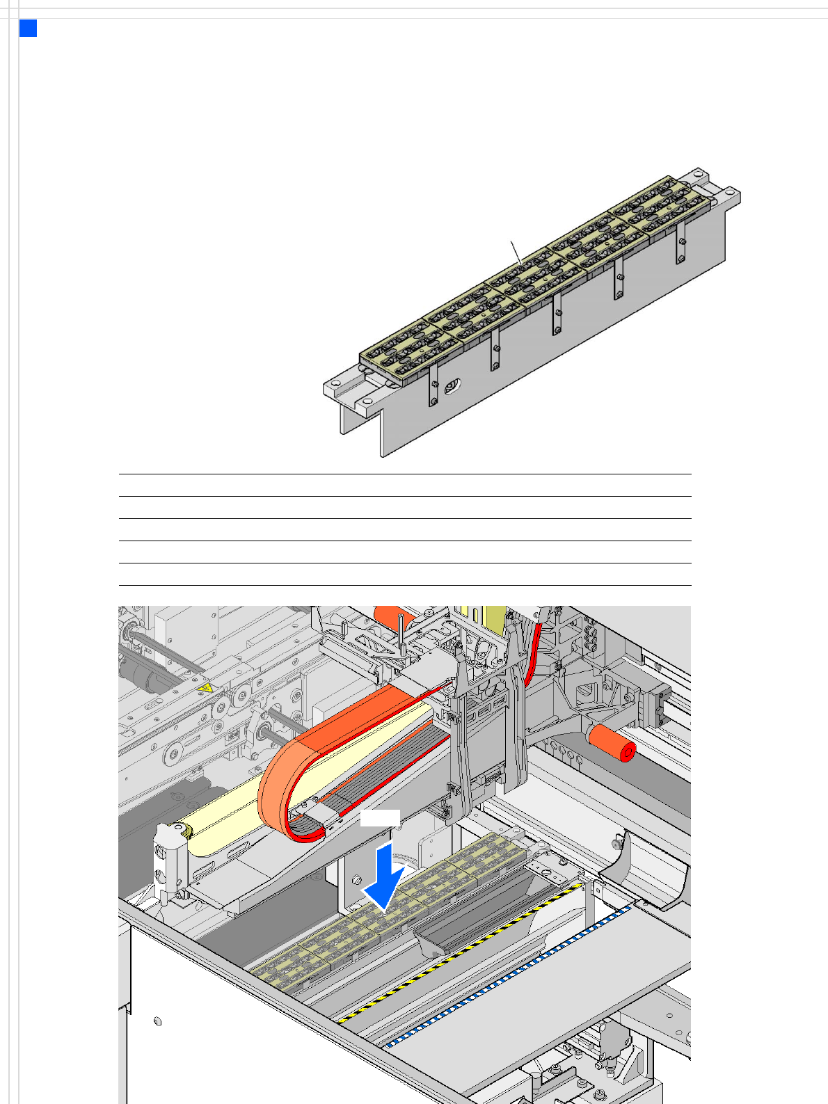
Description
Nozzle changers increase the
flexibility of placement heads
when processing different
components. The nozzle con-
figuration can be quickly
modified for new placement
jobs. Exactly defined posi-
tions and the perfect seating
of the nozzle in the garage
guarantee minimal radial
eccentricity at the placement
head.
Technical data
Dimensions (length x width x height) 472.5 x 63 x 77 mm³
Number of magazines min. 1 / max. 5, each with 12 nozzle holders
Nozzle types 9 xx
Nozzle change time approx. 2s per nozzle
Compressed air connection 0.51 MPa ± 0.01 MPa (5.1 bar ± 0.1 bar)
Nozzle changer for the
12-nozzle Collect & Place head
(5 magazines → 60 nozzle holders in total)
Magazine for 12
type 9xx nozzles
NC12