D4操作手册.pdf - 第16页
16 Comp onent Fe eding SIPLACE D4 Comp onent Changeover Table Description The component c hangeover tabl es ar e st and -alo ne mo d- ules that c an be set up at an external set-u p area with feeder modules. Up to four c…
15
PCB Conveyor
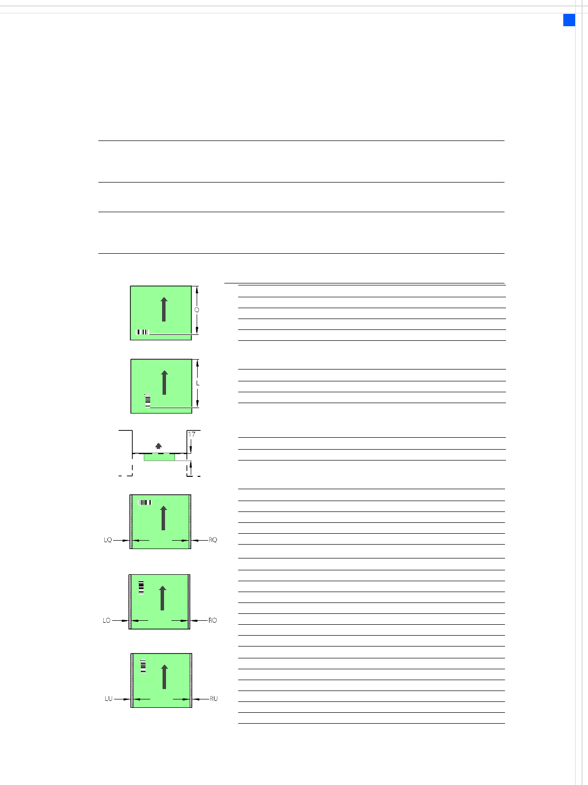
SIPLACE PCB Barcode for Product-Controlled
Production (Option)
Label dimensions Stroke width (W): 0.19 < W ≤ 0.3 mm (corresponds to high and medium
density), stroke length: ≥ 4 mm, length of the barcode template win-
dow: ≤ 90 mm
Recommended
label colors
Coding: black, dark green, dark blue, background: white, beige, yellow,
orange (contrast ratio > 70% to DIN 66236
Code types Code 39, Code 128 / EAN 128, Codabar, 2/5 IATA 2/5 industrial, 2/5
interleaved, UPC, EAN, Pharma Code, EAN Addendum (others available
on request), max. 25 digits, a barcode filter may be defined
Laser scanner
safety
Laser diode 670 nm (red) / 1.2 mW
Laser protection class 2, degree of protection IP65
PCB barcode reader Q [mm]
2D on top 390
1D on top 390
2D on bottom 430
1D on bottom 430
PCB barcode reader L [mm]
1D on top 320 - 350
1D on bottom 380 - 410
PCB barcode reader PCB rear projection [mm]
2D on bottom (dual conveyor) 17
PCB barcode reader LQ [mm] RQ [mm]
2D on top 3 3
1D on top 3 3
2D on bottom 5 5
1D on bottom 5 5
PCB dimensions/conveyor LO [mm] RO [mm]
460 mm SC 3 20
508 mm SC 3 44
216 mm DC1 3 24
242 mm DC1, 380 mm SM1 3 58
216 mm DC2 3 3
242 mm DC2, 380 mm SM2 3 3
PCB dimensions/conveyor LU [mm] RU [mm]
460 mm SC 20 3
508 mm SC 44 3
216 mm DC1 3 3
242 mm DC1, 380 mm SM1 3 3
216 mm DC2 24 3
242 mm DC2, 380 mm SM2 58 3
SC - Single conveyor, DC1/2 - Dual conveyor, track 1/2, SM1/2 - Dual conveyor in Single conveyor mode, track 1/2
Downstream
machine
Upstream
machine
PCB
PCB barcode scanner 1D on top
PCB barcode scanner 1D on bottom
16
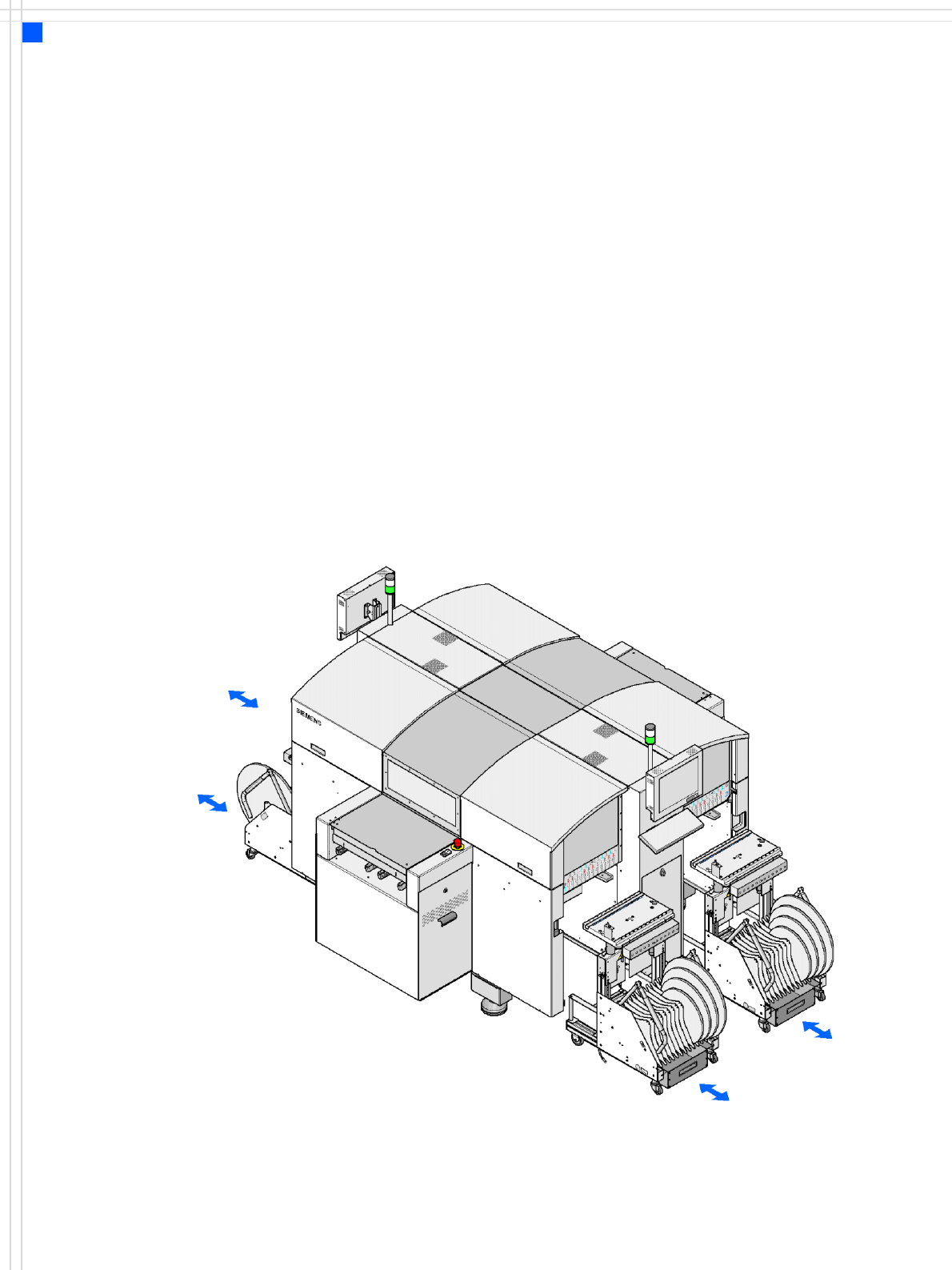
Component Feeding
SIPLACE D4 Component Changeover Table
Description
The component changeover
tables are stand-alone mod-
ules that can be set up at an
external set-up area with
feeder modules. Up to four
component changeover
tables may be docked in the
machine. A component
changeover table can be re-
placed with just a short inter-
ruption of the production
process.
The chassis runs smoothly
and is easy to maneuver. The
component table has a
capacity of up to 12 locations
for 3 x 8 mm S tape feeder
modules. The total capacity
with four component
changeover tables is thus
144 x 8 mm tracks. Bulk case
feeder modules, linear vibra-
tory feeders, dipflux mod-
ules, component disposal
modules and waffle-pack tray
holders can all be set up in
addition to the tape feeder
modules. Dummy feeder
modules are used at un-
assigned locations to protect
the operators. The compo-
nent feeders are at rest dur-
ing the placement process -
allowing tapes to be spliced
without stopping the
machine.
Location 1
Location 3
Location 2
Location 4
17
Component Feeding
Component Changeover Table
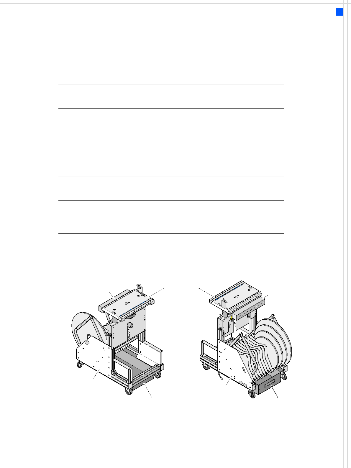
Technical Data
Length
Length with handle folded up
Width
711 mm
871 mm
475 mm
Height of bottom edge of table bed for
830 mm PCB conveyor height
900 mm PCB conveyor height
930 mm PCB conveyor height
950 mm PCB conveyor height
680 mm
750 mm
780 mm
800 mm
PCB transport height 830 mm ± 15 mm (standard)
900 mm ± 15 mm (option)
930 mm ± 15 mm (option)
950 mm ± 15 mm (SMEMA option)
Weight
without feeder modules
with feeder module at all locations
75 kg
130 kg
Reel diameter
standard
maximum
up to 432 mm (17“)
483 mm (19“)
Locations for feeder modules max. 12
Changeover time less than 1 min.
Communication
unit
Tape container
Waste container for pieces of used tape
Component
feeder table
Tape container
Waste container for pieces of used tape
Communication unit