D4操作手册.pdf - 第5页
5 Machine Description Overview Description The SIPLACE D4 high-speed plac eme nt m ach in e c om- bines a h igh placem ent rate with accu racy and flex ibility. It uses the Collect & Place place ment method. The SIPL…

4
SIPLACE D4
Contents
5
Machine Description
Overview
Description
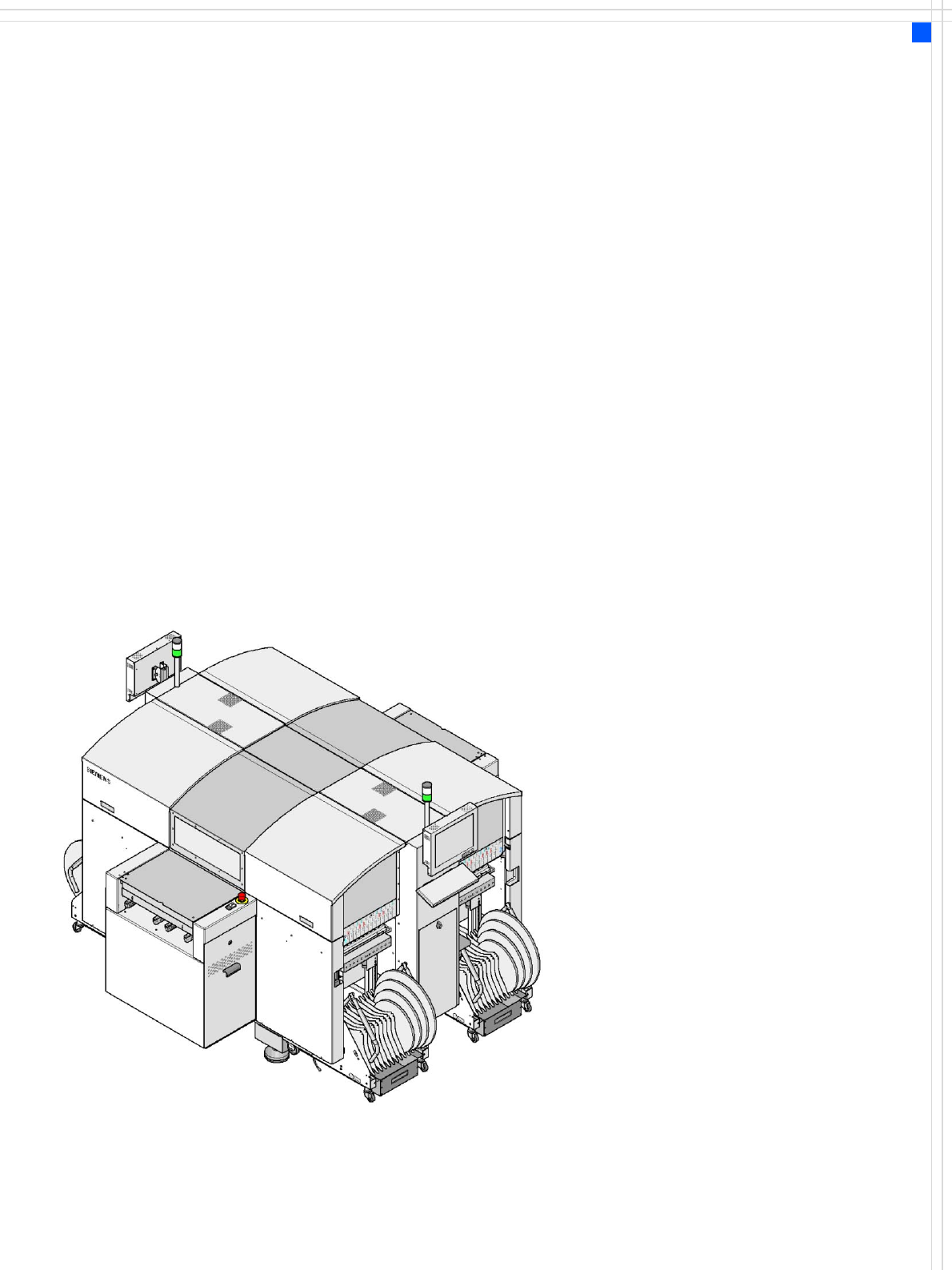
The SIPLACE D4 high-speed
placement machine com-
bines a high placement rate
with accuracy and flexibility.
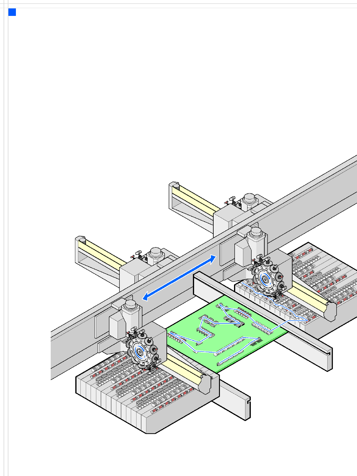
It uses the Collect & Place
placement method.
The SIPLACE D4 placement
machine is equipped with
four gantries which can be
positioned quickly and accu-
rately in the X and Y direc-
tions.
At each gantry there is a
12-nozzle Collect & Place
head. The gantries are com-
bined in pairs to form a com-
mon placement area.
Placement area 1:
Gantries 1 and 4
Placement area 2:
Gantries 2 and 3
The components are optically
centered using a digital
vision module. There are two
different digital component
cameras available for the
placement heads: a standard
camera and a high-resolution
component camera.
A five-piece PCB conveyor,
consisting of input belt, pro-
cessing belt 1, intermediate
belt, processing belt 2 and
output belt, carries the PCB
into the processing position.
As a further variant, it is also
possible to choose between
the single conveyor or flexi-
ble dual conveyor with fixed
side on right or left. The PCBs
are optically centered with
the digital PCB camera.
The moving head picks up
the components from their
stationary feeder, and places
them on the PCB, which is
also stationary. This proven
SIPLACE principle has many
advantages:
• Short down times for refill-
ing or splicing
• Even the smallest compo-
nents are picked up reli-
ably
• The components cannot
slip on the PCB
• Minimal traversing paths
High flexibility, cost-effec-
tiveness and set-up reliability
guarantee that the SIPLACE
D4 placement system will be
highly productive. The mini-
mal down times increase uti-
lization, thus further
increasing productivity.
6
Placement principle
Collect & Place
Machine Description
Extensions
Extensions
The options available to ex-
tend the functionality of the
placement machine include
the following:
• Additional component
changeover tables in-
crease machine utilization
since set-up times can be
reduced by carrying out
preliminary set-up off the
machine.
• The flexible dual conveyor
also increases machine
utilization by eliminating
non-productive PCB trans-
port times.
• Automatic nozzle chang-
ers speed up and optimize
the nozzle configuration
process.
• PCB barcode scanners al-
low the production set-up
to be changed over when
triggered by a new
product.
• The productivity lift imple-
ments the concept of par-
allel placement, and thus
improves the ratio be-
tween productive and
non-productive times.