D4操作手册.pdf - 第20页
20 Comp onent Fe eding Dummy Feeder Modules Dummy feeder m odules for compon ent change over tables from the SIPL ACE D4 The following dummy feeder modul e variants are av ailable for component change over tables from th…
19
Component Feeding
Bulk Case and Vibratory Stick Feeder Modules
Technical Data
Bulk case feeder modules
a
Packaging form Bulk case
Feeder rails Chip 0402, CO height: 0.35 mm
Chip 0402, CO height: 0.50 mm
Chip 0603, CO height: 0.45 mm
Chip 0603, CO height: 0.80 mm
Chip 0805, CO height: 0.45 mm
Chip 0805, CO height: 0.60 mm
Chip 0805, CO height: 0.85 mm
Chip 0805, CO height: 1.25 mm
Micro-Melf: 1.05 ± 0.05 mm
Mini-Melf: 1.4 ± 0.1 mm
Location 1 location for 2 different com-
ponent types
Vibratory stick feeder,
type 3
with control circuit
Number of tracks and width 3 x 9.5 mm
2 x 15 mm
1 x > 15 mm
1 x 30 mm
Location 1 location
a) Fiducial for feeder module position recognition
Description
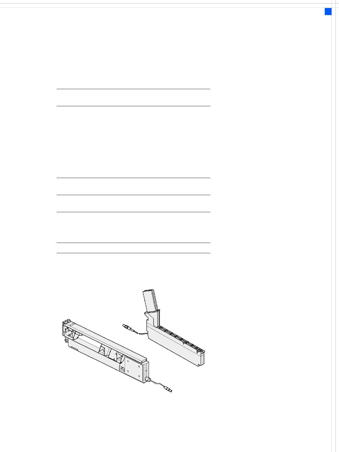
The SIPLACE bulk case feeder
module processes bulk cases
on two tracks. It feeds rectan-
gular and round, passive
components. The PCB maga-
zines (bulk cases) are simply
replaced for refilling - with-
out stopping the machine.
The module essentially con-
sists of the basic element plus
two feeder rails and PCB mag-
azines to suit the component
type and height. The compo-
nents are separated and fed
along the rails by compressed
air.
The principle of the fixed
component table has proven
its worth, even when bulk
cases are used: the vibrations
that can occur with other
placement machine concepts
can have a highly detrimental
effect on the component
quality due to abrasion, for
example.
Even with stick magazines,
the stationary component
supply has significant advan-
tages: the universal vibratory
stick feeder can be topped up
during placement.
Bulk case feeder module
Vibratory -
stick feeder, type 3
20
Component Feeding
Dummy Feeder Modules
Dummy feeder modules for component changeover tables
from the SIPLACE D4
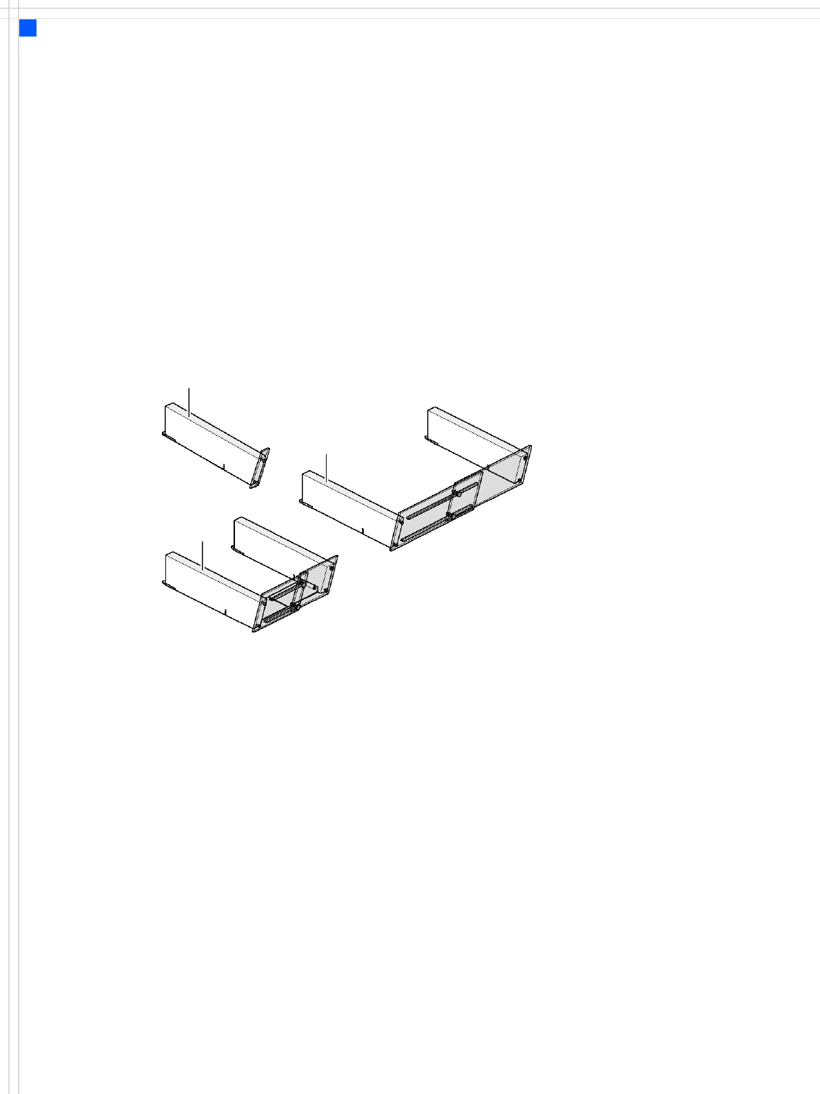
The following dummy feeder module variants are available for
component changeover tables from the SIPLACE D4:
SIPLACE dummy feeder module for 1 location
SIPLACE dummy feeder module for 6 - 10 locations
SIPLACE dummy feeder module for 11 - 20 locations
Dummy feeder module for 1 location
Dummy feeder module for
6 - 10 locations
Dummy feeder module for
11 - 20 locations
Danger
To ensure that your SIPLACE
placement machine runs
safely, a feeder must be
assigned to every location on
the component changeover
table. If you do not have
enough feeder modules, then
you should use dummy feeder
modules as space holders.
21
Vision Sensor Technology
PCB Position Recognition
Technical data
PCB fiducials
Local fiducials
Library memory f.
recognition of
bad panels
up to 3 (subpanels and multiple
panels)
up to 6 for the Long board option
(Optional PCB fiducials are output by
the optimization.)
up to 2 per PCB (may be of different
type)
up to 255 fiducial types per subpanel
Image analysis Edge detection method (Singular fea-
ture) based on grayscale values
Lighting method Front lighting
Fiducial recogni-
tion time
0.1 s
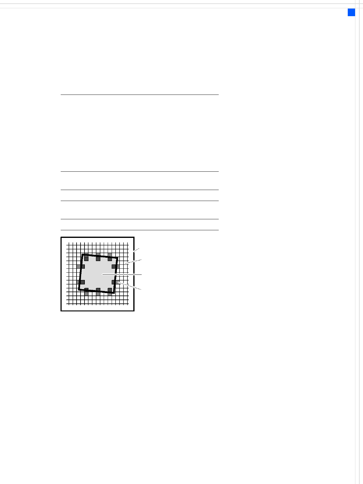
Field of vision 5.78 x 5.78 mm
Camera’s field of view
Pixel
Ink spot, e.g. square
Evaluation window
Geometrical Alignment
The size of the fiducial is pro-
grammed at the station com-
puter. From this time on form
and size of the fiducial is
defined and known.
With these data the PCB
vision module is able to
search and recognize the
fiducial at the predefined
position on the PCB or ceram-
ic substrate without further
assistance. For this reason it
places several small evalua-
tion windows at the assumed
border of the fiducial. Within
these evaluation windows
the vision system looks for
contrast transitions between
bright and dark. After finding
such contrasts the actual
position of the fiducial can be
assigned by comparison with
the predefined – and thus
known – shape and size.
The analysis operations can
be used to determine any off-
set with respect to the DE-
SIRED position in the X and Y
directions and the angular
position. Alternatively, a fidu-
cial may be taught as a pat-
tern.
Additional functions of the
PCB vision module are recog-
nition of the position of the
feeder modules and ceramic
substrate (optional) and
recording of the machine
data including mapping.
The bad board detector
(GOOD/SCRAP scan) is also
moved over the ink spot
using the PCB vision module.
Description
SIPLACE has a number of
vision modules and a central
vision system to evaluate the
recorded image data ensur-
ing high placement accuracy.
At the machine's X-gantry
the PCB vision module is
mounted. It is used to find
the PCB's positioning-offsets
within the conveyor system.
This vision module is also
required to measure the
machine origin and/or the
feeder module positions on
one side of the table.
Each vision module consists
of a single CCD camera with
integrated lighting and
optics. The offsets in the
position of the PCBs are
determined with the help of
at least two but generally
three reference fiducials on
the PCB. When the PCB
arrives at the placement area
the positioning system with
its PCB vision module moves
to the programmed fiducial.
The edge detection method
allows to choose predefined
fiducials from a menu (e.g.
cross, circle, square).