D4操作手册.pdf - 第24页
24 Technical Data Siemens Signal Interface Connector Assignment Signal interface (20-pole ribbon cable con nector) Upstream station X1 Do wnstream station X2 Pin 1 Reserved Pin 1 Reser ved Pin 2 GND 24 VDC Pin 2 Reser ve…
23
Vision Sensor Technology
Bad Board Recognition
Position Recognition for Feeder Modules
Description
In the cluster technology
each subpanel is assigned an
ink spot. If this is present dur-
ing the measurement via the
PCB vision module, the corre-
sponding subpanel is popu-
lated.
It is also possible to accom-
plish the population of the
subpanel when the ink spot is
missing. With this function it
is possible to eliminate costs
due to unnecessary popula-
tion of faulty subpanels.
Global Ink Spot
Each GOOD/SCRAP scan takes
some time, and the time re-
quired is even greater if there
are a large number of sub-
panels on a PCB. Using the
global ink spot can result in a
significant reduction of these
secondary times.
The PCB vision module
searches at positions taught
before for the defined fidu-
cial. In case of recognition
there is no following evalua-
tion of subpanels. The sys-
tem allows the operator to
choose also the reverse inter-
pretation.
Recognition of the position
of the feeder modules
The pick-up position of the
components can be deter-
mined precisely with the aid
of the position recognition
for the feeder. The offset in
position relative to the stored
ideal position is determined
on the basis of fiducials on
the feeder modules using the
PCB vision module.
This provides very high pick-
up reliability even for the
very first component, which
is particularly important for
small components.
Ink Spot Criteria
Methods • Synthetic fiducial recognition method
• Mean grayscale value
• Histogram method
• Template matching
Shapes and sizes of fiducials/structures for
synthetic fiducials
other methods
for dimensions of synthetic fiducials, see page 22
min. 0.3 mm, max. 5 mm
Masking material good coverage
Recognition time depends on the method: 20 ms - 0.2s

24
Technical Data
Siemens Signal Interface
Connector Assignment
Signal interface (20-pole ribbon cable connector)
Upstream station X1 Downstream station X2
Pin 1 Reserved Pin 1 Reserved
Pin 2 GND 24 VDC Pin 2 Reserved
Pin 3 + 24 VDC Pin 3 Reserved
Pin 4 Reserved Pin 4 Reserved
Pin 5 Reserved Pin 5 GND 24 VDC
Pin 6 Reserved Pin 6 + 24 VDC
Pin 7 Reserved Pin 7 Reserved
Pin 8 Reserved Pin 8 Reserved
Pin 9 Reserved Pin 9 Reserved
Pin 10 Reserved Pin 10 Reserved
Pin 11 Interfering signal loop Pin 11 Interfering signal loop
Pin 12 Interfering signal loop Pin 12 Interfering signal loop
Pin 13 GND 24 VDC Pin 13 GND 24 VDC for permission /
arrived (galvanic isolation)
Pin 14 Arrived Pin 14 Arrived
Pin 15 Permission Pin 15 Permission
Pin 16 Reserved Pin 16 Reserved
Pin 17 Reserved Pin 17 Reserved
Pin 18 Transferred Pin 18 Transferred
Pin 19 Request Pin 19 Request
Pin 20 GND 24 VDC for request / trans-
ferred (galvanic isolation)
Pin 20 GND 24 VDC
25
Technical Data
Siemens Signal Interface
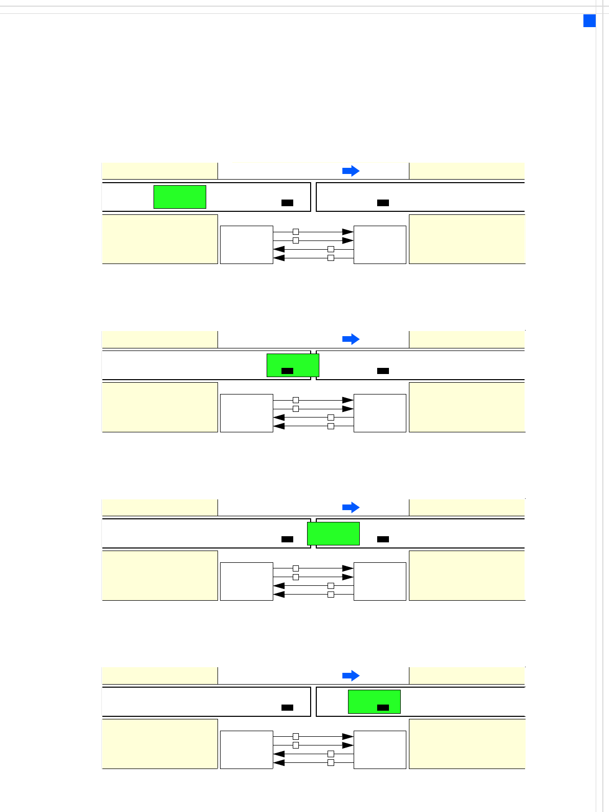
Signal Curve
1
.
Af
ter sw
i
tc
hi
ng on t
h
e stat
i
on
Transport direction
Belt n Belt n+1
PCB sensor PCB sensor
Station n transports
PCB to the transfer posi-
Belt n running Belt n+1 stopped
Request
Transferred
Permission
Arrived
Request
Transferred
Permission
Arrived
Station n+1
is ready to receive PCBs
0
0
1
0
2. The PCB transfer has started
Transport direction
Belt n Belt n+1
PCB sensor
Station n transfers
PCB to Station n+1
Belt n running Belt n+1 running
Request
Transferred
Permission
Arrived
Request
Transferred
Permission
Arrived
Station n+1 expects
PCB from station n
1
0
1
0
3. PCB is transferred
Transport direction
Belt n Belt n+1
PCB sensor PCB sensor
Station n has
just transferred the PCB
Belt n stopped Belt n+1 running
Request
Transferred
Permission
Arrived
Request
Transferred
Permission
Arrived
Station n+1 expects PCB
from station n, but PCB
has not yet arrived.
0
1
1
0
PCB sensor
4. PCB transfer is complete
Transport direction
Belt n Belt n+1
PCB sensor PCB sensor
Station n
Belt n stopped Belt n+1 running
Request
Transferred
Permission
Arrived
Request
Transferred
Permission
Arrived
Station n+1
PCB arrived
0
0
0
1