D4操作手册.pdf - 第4页
4 SIPLACE D4 Contents

3
SIPLACE D4
Contents
SIPLACE D4 3
Contents 3
Machine Description 5
Overview 5
Extensions 6
Technical Data 7
Placement Head 8
12-Nozzle Collect & Place Head for High-Speed Placement 8
Technical Data 9
Nozzle Changers 10
Technical Data 10
PCB Conveyor 11
Single Conveyor 11
Technical Data 12
Flexible Dual Conveyor 13
Technical Data 14
SIPLACE PCB Barcode for Product-Controlled Production (Option) 15
Component Feeding 16
SIPLACE D4 Component Changeover Table 16
Technical Data 17
S Tape Feeder Modules 18
Bulk Case and Vibratory Stick Feeder Modules 19
Dummy Feeder Modules 20
Vision Sensor Technology 21
PCB Position Recognition 21
Bad Board Recognition 23
Position Recognition for Feeder Modules 23
Technical Data 24
Siemens Signal Interface 24
Connector Assignment 24
Signal Curve 25
SMEMA Interface 26
Connector Assignment 26
Signal Curve 27
Electrical Ratings and Compressed Air Supply 28
Electrical Connection, Interfaces and Compressed Air Connection 29
Dimensions and Set-up Conditions 30
Placement System’s Center of Gravity 31
Spacing Distances for Single Conveyor 32
Spacing Distances for Dual Conveyor 33
Transport and Delivery Configuration 34
Sample Configuration 35
Option List for the SIPLACE D4 36

4
SIPLACE D4
Contents
5
Machine Description
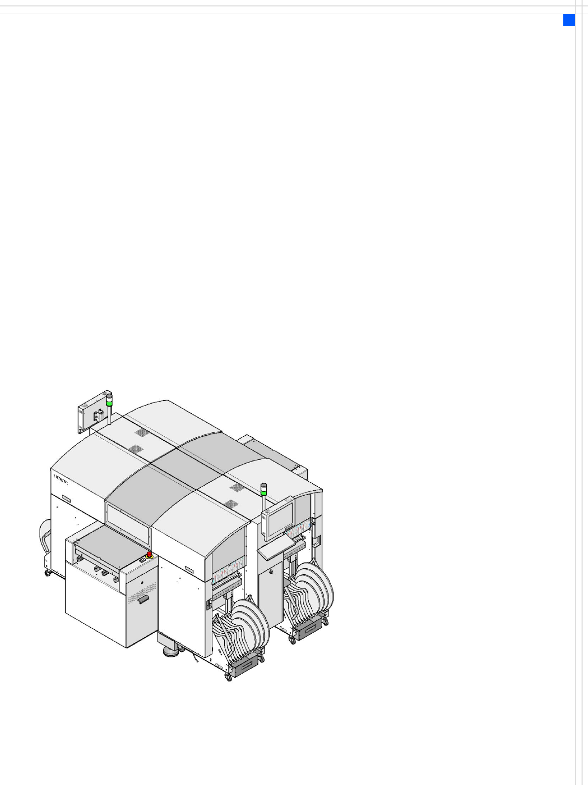
Overview
Description
The SIPLACE D4 high-speed
placement machine com-
bines a high placement rate
with accuracy and flexibility.
It uses the Collect & Place
placement method.
The SIPLACE D4 placement
machine is equipped with
four gantries which can be
positioned quickly and accu-
rately in the X and Y direc-
tions.
At each gantry there is a
12-nozzle Collect & Place
head. The gantries are com-
bined in pairs to form a com-
mon placement area.
Placement area 1:
Gantries 1 and 4
Placement area 2:
Gantries 2 and 3
The components are optically
centered using a digital
vision module. There are two
different digital component
cameras available for the
placement heads: a standard
camera and a high-resolution
component camera.
A five-piece PCB conveyor,
consisting of input belt, pro-
cessing belt 1, intermediate
belt, processing belt 2 and
output belt, carries the PCB
into the processing position.
As a further variant, it is also
possible to choose between
the single conveyor or flexi-
ble dual conveyor with fixed
side on right or left. The PCBs
are optically centered with
the digital PCB camera.
The moving head picks up
the components from their
stationary feeder, and places
them on the PCB, which is
also stationary. This proven
SIPLACE principle has many
advantages:
• Short down times for refill-
ing or splicing
• Even the smallest compo-
nents are picked up reli-
ably
• The components cannot
slip on the PCB
• Minimal traversing paths
High flexibility, cost-effec-
tiveness and set-up reliability
guarantee that the SIPLACE
D4 placement system will be
highly productive. The mini-
mal down times increase uti-
lization, thus further
increasing productivity.