Printer 710_810 v8 Transport Rails Module.pdf - 第13页
TRANSPORT RA ILS MODULE ADJUS TMENT S AND SETT INGS Chapter Issue 6 Oct 06 Technical Reference Manual 16.13 Board Clamp Set ting WARNING BOARD CLAMPS. EXTREME CAR E MUST BE EXERCISED WHEN W ORKING IN THE TOOLING AREA OF …
TRANSPORT RAILS MODULE
ADJUSTMENTS AND SETTINGS
16.12 Technical Reference Manual Chapter Issue 6 Oct 06
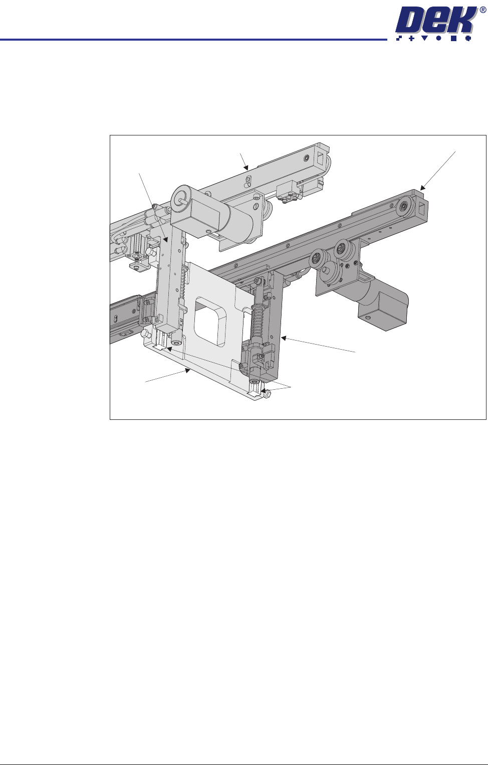
2. Using a pair of rail parallelism H jigs (DEK Pt No 158109) fit the jigs to the
front transport rail left and right leg linear guides. Ensure the linear guides
fit snugly in the jig slots.
3. Move the rear transport rail forwards, towards the front rail, until the rear leg
linear guides fit into the slots of the H jigs.
4. If both sets of linear guides fit snugly in the slots of the jigs, the rear transport
rail is parallel to the front rail, go to Step 11.
5. If either or both jigs do not fit, remove the H jigs and, carry out the Front Rail
Parallelism check as detailed earlier in this chapter.
6. Refit the H jigs.
7. If both sets of linear guides fit snugly in the slots of the jigs, the rear transport
rail is parallel to the front rail, go to Step 11.
8. If the linear guides still do not fit in the jig slots loosen the eight rail leg
bearing block securing screws.
9. Reposition the rear rail until the linear guides fit snugly in the jig slots.
10. Tighten the rail leg bearing block securing screws loosened in Step 8.
11. Remove the H jigs and refit the machine panels removed in Step 1.
Front Rail
Rear Rail
Linear Guide Rails
Rear Right Transport Rail Leg
H Jig
View on Front Right Hand Side
Front Right
Transport
Rail Leg
TRANSPORT RAILS MODULE
ADJUSTMENTS AND SETTINGS
Chapter Issue 6 Oct 06 Technical Reference Manual 16.13
Board Clamp Setting
WARNING
BOARD CLAMPS. EXTREME CARE MUST BE EXERCISED WHEN WORKING IN
THE TOOLING AREA OF THE MACHINE TO AVOID INJURY. THE FOILS ON THE
FRONT AND REAR BOARD CLAMPS ARE VERY SHARP.
NOTE
This setting is factory set and shouldn’t normally need to be adjusted.
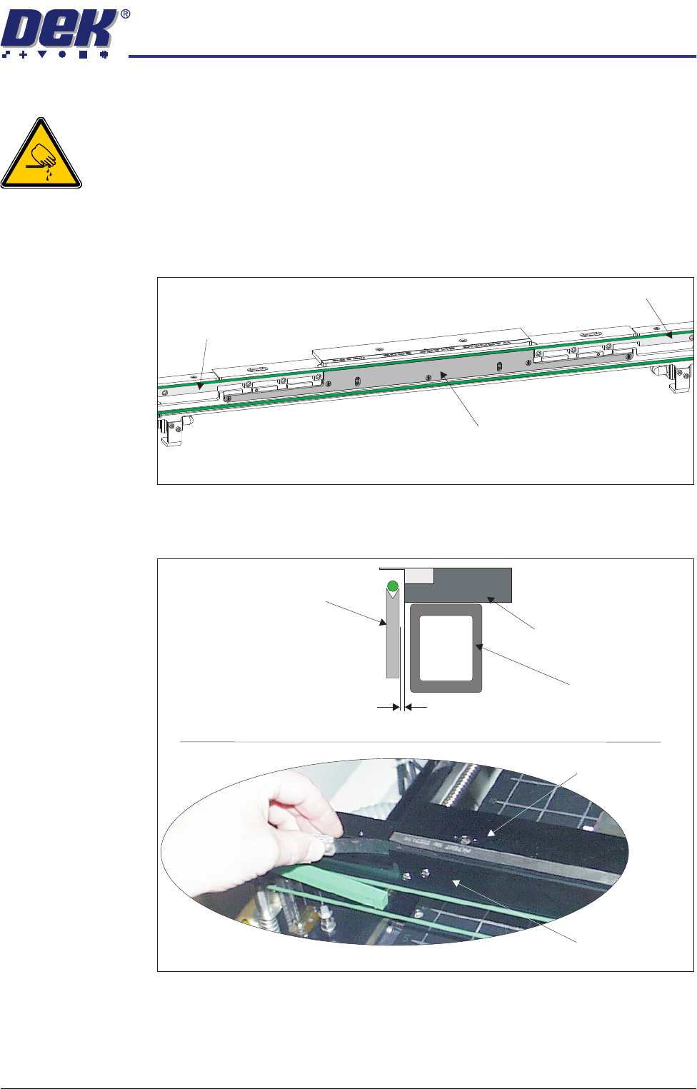
1. Remove the belt guide from either side of the belt support plate.
2. Using feeler gauges, check that the gap between the rear board clamp and
the belt support plate is set between 0.325mm ±0.025mm. Ensure that the
rear board clamp is parallel to the belt support plate.
3. If adjustment is necessary, go to Step 8 for 250mm board clamps and
continue with Step 4 for 500mm board clamps.
Belt Support Plate
Belt Guide
Belt Guide
View on Rear Rail
Cross Section of Rear Rail Assembly
View on Rear Board Clamp
Rear Board Clamp
Belt Support Plate
Belt Support Plate
Rear Board Clamp
Moving Rail
0.3mm - 0.35mm
TRANSPORT RAILS MODULE
ADJUSTMENTS AND SETTINGS
16.14 Technical Reference Manual Chapter Issue 6 Oct 06
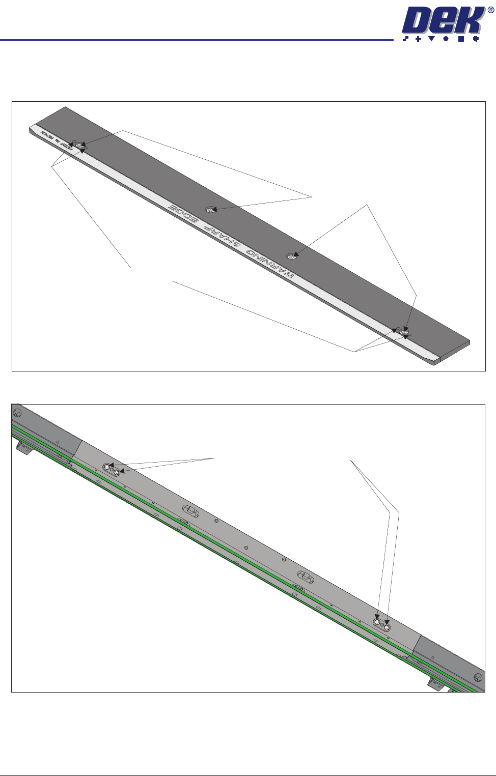
4. Remove the four board clamp securing screws and lift off the board clamp.
Retain the four screws.
5. Slacken the two location plate securing screws.
6. Place the board clamp in position, but do not fit the securing screws.
7. Go to Step 9.
500mm Board Clamp Mechanism
Board Clamp Securing Screws
Access Holes
View on Rear Rail (Board Clamp Removed)
Location Plate Securing Screws