西门子SIPLACE HS 50-设备参数_EN.pdf - 第12页
10 PCB Transpor t Direction Description Thanks to reduced non-productive times the dual PCB conveyor can substantially increase the through- put, depending on the program. It makes i t possible to tra nsport two PCBs thr…
9
PCB Transport
Direction
Description
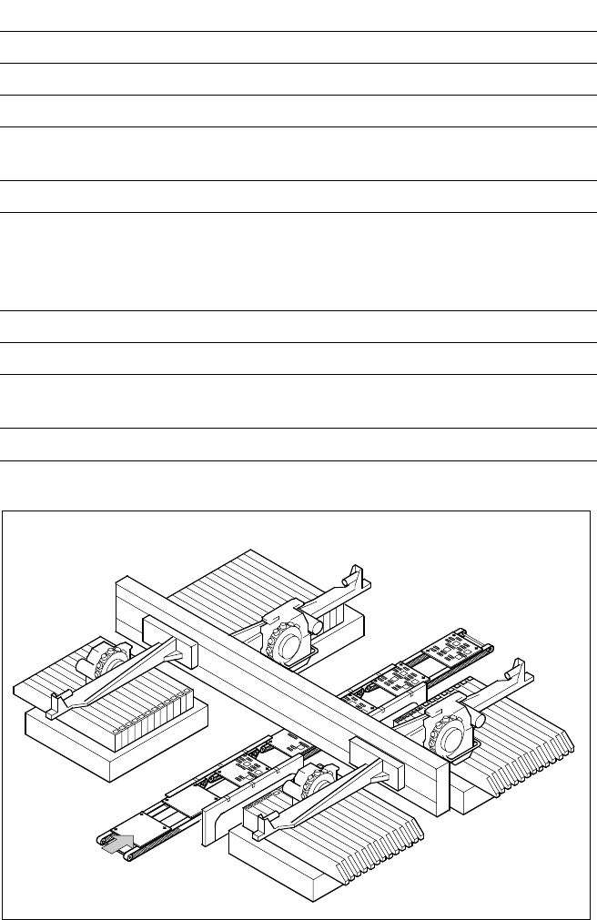
On SIPLACE HS-50 the in-line
conveyor system guarantees a
quick adjustment to new PCB
widths. The change is made either
at the station computer using the
menu function or from the line
computer via the automatic width
adjustment unit.
As standard the SIPLACE place-
ment systems are available with a
single conveyor system.
PCB Conveyor:
Single Conveyor
PCB Conveyor
Technical Data
PCB dimensions See table on page 3
PCB thickness 0.5 to 4.5 mm
Max. PCB weight 3 kg
Max. PCB warpage Top: 4.5 mm - PCB thickness
Bottom: 0.3 mm + PCB thickness
Free space on PCB bottom side 40 mm
PCB conveyor height
830
± 15 mm (Standard)
900
± 15 mm (Option)
930
± 15 mm (Option)
950
± 15 mm (Option) SMEMA
Fixed conveyor edge Right (standard); left (option)
Type of interface Siemens (standard); SMEMA (option)
Component-free PCB
handling edge
3 mm
PCB loading time 2.5 s
10
PCB Transport
Direction
Description
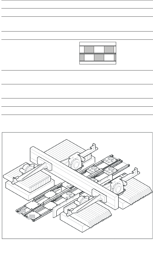
Thanks to reduced non-productive
times the dual PCB conveyor can
substantially increase the through-
put, depending on the program. It
makes it possible to transport two
PCBs through the machine.
In the asynchronous mode of
transport a PCB is moved into the
machine in “slack time” while an-
other of the same PCB is being
populated. The non-productive
time caused by the PCB transport
is therefore completely eliminated.
The increase in placement speed
to be anticipated is between 10
and 30%, depending on the com-
ponents placed on the PCB.
PCB Conveyor:
Dual Conveyor
Technical Data
PCB dimensions See table on page 3
Fixed conveyor edge Right (standard), left (option)
Asynchronous Transport on Dual Conveyor
Transport mode Asynchronous
View
Placement program
per conveyor
same or different
PCB width
per conveyor
same
Ink spot recognition possible
Automatic width adjustment possible
Dual Conveyor with Asynchronous Transport
11
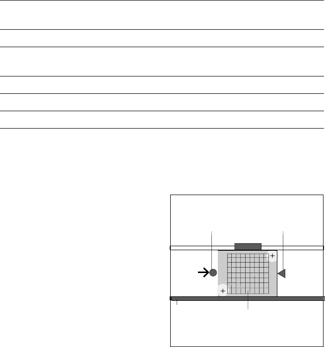
Description
Like the PCB vision module, optical
centering of ceramic substrate is
conducted with the aid of refer-
ence marks (fiducials). Depending
on the contrast ratio the machine
activates a standard lighting or the
oblique lighting.
§ On ceramic and CM blue light.
§ On flexible PCBs using vision
module without IF-filter infrared
light.
PCB Conveyor:
Ceramic Substrate Centering (Option)
Technical Data
Substrate dimensions 50 x 50 mm
2
to 101.6 x 177.8 mm
2
/
2" x 2" to 4" x 7"
Substrate thickness 0.5 to 1.5 mm
Substrate model Unscribed (no difficulty)
Scribed (after test)
Contact in conveyor 2.5 mm
Substrate bottom clearance 12 mm
Compressed air connection 5.5 bar
Optical Centering via PCB Camera
and Mechanical Fixation
Fixed
Transport
Side
Stopper
Ceramic
Substrate
X-Centering