西门子SIPLACE HS 50-设备参数_EN.pdf - 第14页
12 Restric tions for Bar C ode Readin g of PCB Sizes 460 x 460 mm 2 Description The SIPLACE PCB b ar code scan- ner supports the flexible produc- tion of SMD products and en- hances placement re liability. It recognizes …
11
Description
Like the PCB vision module, optical
centering of ceramic substrate is
conducted with the aid of refer-
ence marks (fiducials). Depending
on the contrast ratio the machine
activates a standard lighting or the
oblique lighting.
§ On ceramic and CM blue light.
§ On flexible PCBs using vision
module without IF-filter infrared
light.
PCB Conveyor:
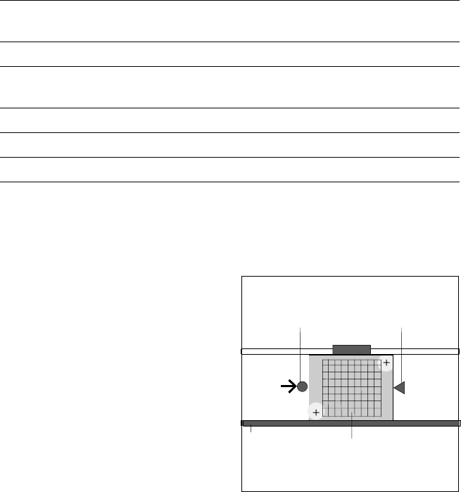
Ceramic Substrate Centering (Option)
Technical Data
Substrate dimensions 50 x 50 mm
2
to 101.6 x 177.8 mm
2
/
2" x 2" to 4" x 7"
Substrate thickness 0.5 to 1.5 mm
Substrate model Unscribed (no difficulty)
Scribed (after test)
Contact in conveyor 2.5 mm
Substrate bottom clearance 12 mm
Compressed air connection 5.5 bar
Optical Centering via PCB Camera
and Mechanical Fixation
Fixed
Transport
Side
Stopper
Ceramic
Substrate
X-Centering
12
Restrictions for Bar Code Reading
of PCB Sizes 460 x 460 mm
2
Description
The SIPLACE PCB bar code scan-
ner supports the flexible produc-
tion of SMD products and en-
hances placement reliability. It
recognizes all code types in gen-
eral use for industrial applications.
The laser scanner reads the bar
code label on the top and/or bot-
tom of each PCB moving during
transport. On the basis of the bar
code information the line computer
automatically selects the correct
placement program from the pre-
viously prepared bar code assign-
ment list and sends it to the sta-
tion. This procedure is performed
in slack time while a PCB already in
the machine is being populated. If
a number of PCBs with the same
bar code are moved in one after
the other, the program is only
transferred the first time. The fol-
lowing preconditions apply for all
products which are to be manufac-
tured with the aid of the PCB bar
code:
§ identical component set-up at
the individual machines in the
line
§ all PCBs of same width.
The bar code filter can be utilized,
if only certain information con-
tained in the bar code is relevant.
PCB Conveyor:
PCB Bar Code for Production-Controlled Manufacturing
(Option)
Technical Data
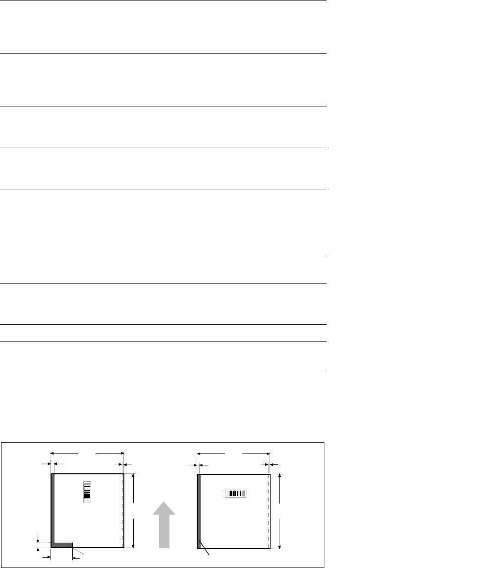
Bar-code-free PCB edge 3 mm on left and right parallel to PCB
transport direction (the additional restric-
tions shown in figure at the bottom apply
for scanning the bar code from above)
Label dimensions
Stroke width: W: 0.19 < W
≤ 0.3 mm
(corresponds to high + medium density)
Stroke length:
≥ 4 mm
a
Length of scanning window: ≤ 90 mm
Label alignment on PCB
b
Parallel or at right angles to the PCB
transport direction, preferably next to
fixed conveyor side
Recommended label colors
(contrast ratio > 70%
as per DIN 66236)
Color coding: black, dark green or dark blue
Background: white, beige, yellow, orange
Code types Code 39, Code 128 / EAN 128,
Codabar, 2/5 IATA 2/5 industrial,
2/5 interleaved, UPC, EAN,
Pharma Code, EAN Addendum
(more upon request)
Complete bar code Max. 25 characters
Definition of a bar code filter possible
Safety of the laser scanner Laser diode 670 nm (red) / 1 mW
Laser protection class 2, degree of
protection IP65
Station and line software from Version 502.xx
Scan-in/analysis time Cycle time (T < 1 s), in parallel to the
placement of preceding PCB
a) This value can only be met if the bar code label on the PCB moves through the bar code scanner at
right angles to the machine’s direction of transport.
b) Depending on where the bar code label is located on the PCB, the position of the bar code scanner
can be easily adjusted in the input conveyor belt.
460 460
18.5 3
118
2
3
8
3
restricted
restricted
PCB
Transport
Direction
460
460
13
Description
SIPLACE HS-50 is equipped with
four stationary component tables,
one for each placement head. With
these four tables SIPLACE HS-50
can accommodate a total of 144
different 8 mm part numbers.
On the changeover tables tape
feeders and Bulk Case feeders
can be positioned. For safety rea-
sons tracks not in use should be
equipped with guards for feeder
locations.
Component feeders are stationary
during the placement process. This
allows for the replenishment of
both tape and bulk components
during machine operation.
For the changeover, individual
feeders or entire changeover ta-
bles can be exchanged without the
use of tools or external lifts. Job
changeover times can be dramati-
cally reduced with the use of addi-
tional feeder tables. This will allow
large set-ups to be completed off
line without impacting machine
production time
Using component bar codes with
the optional Component Bar Code
Scanner guarantees the correct
allocation of component to track.
Changeover tables are equipped
with rollers and an integrated
pneumatic lifting device which
eliminates the need of an external
lifting cart as with other equip-
ment. Exchanging the tables takes
less than 2 minutes per module.
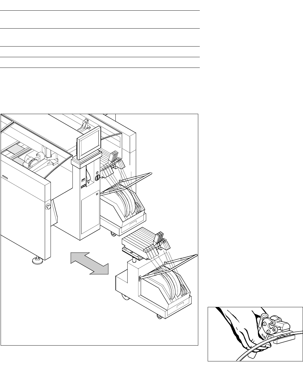
Component Supply:
Changeover Table
Exchange of a Component Changeover Table
Mobile
Changeover
Table
Technical Data
Component feeder tables
(exchangeable)
4 tables per machine
compatible only with SIPLACE HS-50
Feeder location 12 feeders 3 x 8 mm per table =
144 tracks of 8 mm per machine
Feeder modules SIPLACE tape and bulk feeders
Accessories Tape container, waste container,
Splicing Tool