西门子SIPLACE HS 50-设备参数_EN.pdf - 第8页
6 Placement Heads: Placement Accuracy Component Range Placement Accu racy a Placement Head Placement Accuracy 12-Nozzle Collect & Place Head X/Y Accuracy 67.5 µm 3 Sigma Rot.-Accuracy 0.525° X/Y Accuracy 90.0 µm 4 Si…
5
Description
The 12-Nozzle placement head op-
erates on the Collect & Place prin-
ciple.
Each of the four X/Y-gantries
features one high-speed 12-Nozzle
Collect & Place Head.
At two gantries components are
picked up while at the other two
gantries components are placed.
Each head features an intelligent
Z-axis, Theta-axis for rotation and
vacuum monitoring.
Z-axis is learning both pick-up and
placement Z-height and thus opti-
mizes speed without compromis-
ing the programmed placement
forces.
Vacuum monitoring ensures low
component reject rates and high
quality placement.
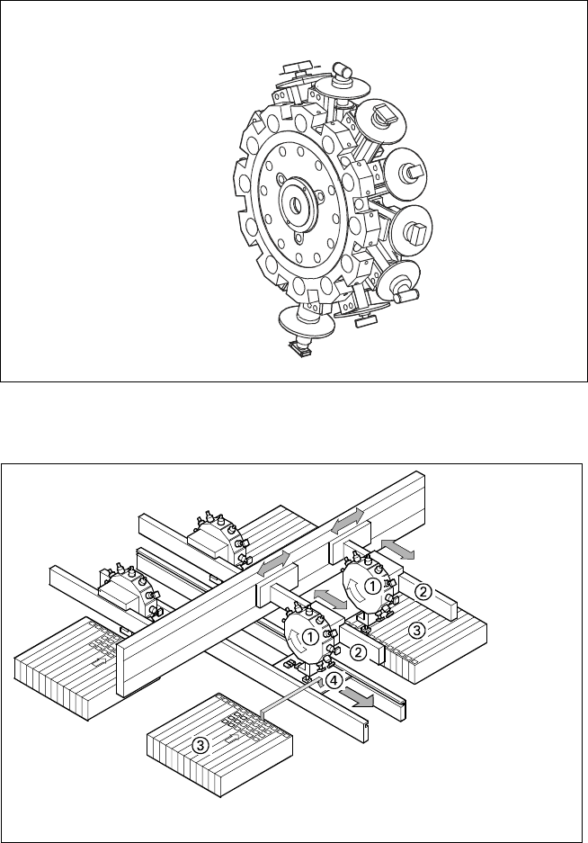
Placement Heads
Placement Principle of SIPLACE HS-50
➀ 12-Nozzle Collect & Place Head
➁ X-/Y-Gantry System
➂ Fixed Component Supply
➃ Fixed PCB
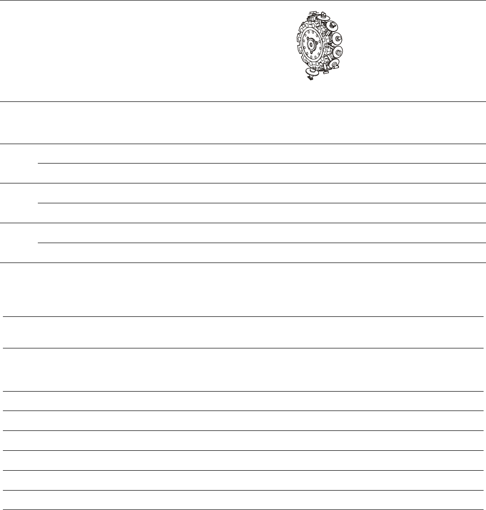
12-Nozzle
Collect & Place
Head
12-Nozzle Collect & Place Head for Very High Speed Placement
6
Placement Heads:
Placement Accuracy
Component Range
Placement Accuracy
a
Placement Head
Placement Accuracy
12-Nozzle
Collect & Place Head
X/Y Accuracy 67.5 µm
3
Sigma
Rot.-Accuracy 0.525°
X/Y Accuracy 90.0 µm
4
Sigma
Rot.-Accuracy 0.700°
X/Y Accuracy 135.0 µm
6
Sigma
Rot.-Accuracy 1.050°
a) As defined in “Scope of Service and Delivery SIPLACE”.
Component Range
12-Nozzle
Collect & Place Head
Component size
0.6 x 0.3 mm
2
to
18.7 x 18.7 mm
2
Max. component height 6 mm
Max. component weight 2 gr
Placement force 2.4 - 5.0 N
Performance See table on page 3
Min. pitch lead / bump 500 / 350 µm
Min. ball / bump diam. 200 µm
7
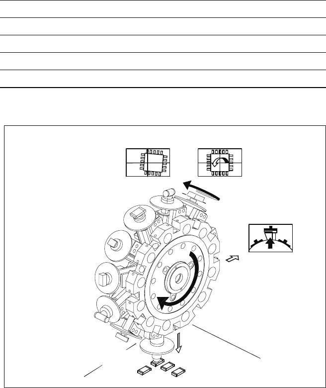
12-Nozzle Collect & Place Head for Very High Speed Placement
Component Pick-Up/
Placement
Segment
Removal
Point
Turning to
the Placement
Position
Component
Vision
Description
The 12-Nozzle placement head op-
erates on the Collect & Place prin-
ciple. In contrast to classic chip
shooters, the 12 vacuum nozzles
of the SIPLACE Collect & Place
head rotate around a horizontal
axis. In addition to space savings
this offers the following benefits:
Due to the small diameter com-
pared to chip shooters, the cen-
trifugal forces are significantly
lower. The results are high-speed,
reliable placement and the same
cycle time for all components.
Components are picked up and
placed reliably with the aid of vac-
uum followed by a gentle air kiss.
A number of vacuum tests moni-
tors if the component has been
picked up and placed accurately.
Various control and self-learning
functions further enhance the de-
pendability of the system:
§ The optical recognition of feeder
positions records the exact posi-
tion of the feeder table.
§ A camera on the placement head
(component vision module) de-
termines the exact position of
each component on the nozzle.
§ For every feeder the pick-up
offsets are averaged over the
last ten pick-ups. This enables
the head to dial-in on the precise
pick point for each component.
§ In addition, the package form is
also checked. If the actual geo-
metric dimensions of the com-
ponent do not correspond to
those programmed, the compo-
nent is rejected.
§ Components rejected by the vi-
sion system are dumped into a
bin, reject feeder or matrix tray.
Any rejected component gets
automatically placed during a
repair run.
§ Warpage of the PCB is accom-
modated by sensor stop acti-
vated z-axis placement. The sys-
tem also keeps the last ten
positions of the z-axis at com-
ponent placement and uses the
average of these values to im-
prove the drive down and place
speed of the cycle.
Placement Heads:
12-Nozzle Collect & Place Head for Very High Speed
Component Placement
Technical Data
Component range See table on page 6
Stroke of Z-axis max. 16 mm
Programmable placement force 2.4 to 5.0 N
Benchmark placement rate 12,500 cph
Placement accuracy See table on page 6