西门子SIPLACE HS 50-设备参数_EN.pdf - 第24页
22 Description The standard component vision module is dire ctly integrated into the Collect & Place Head. While the component is cycling into the next station of the Collect & Place Head, the recorded image is e…

21
Description
The component vision module in-
tegrated into the placement head
significantly contributes to place-
ment precision and reliability. It
dependably recognizes all package
forms (= geometric dimensions of
the component) which are illumi-
nated at various angles from three
planes in the case of the 12-Nozzle
Collect & Place Head. For optimal
illumination of each component,
the brightness of the lighting of the
planes can be adjusted individually
in 256 increments.
Aside from the dimension of the
SMD module, the vision system
determines the number of leads
and their pitch (lateral IC lead bend)
as well as the offset of the place-
ment angle and the X-/Y-axis. Un-
suitable components are rejected
and automatically added later in a
repair cycle. Offsets in placement
angle and X-/Y-axis are corrected at
the turning station of the Collect &
Place Head or via the gantry axes.
From the positions of a number of
components in one track a relevant
offset in the pick-up position on
the X-/Y-axis is calculated. This off-
set is taken into account during
subsequent component pick-up
steps due to the self-learning prin-
ciple.
Prior to placement, the required
geometric dimensions of a com-
ponent type are entered into the
GF editor, creating a synthetic
model of the SMD chip. This task
is facilitated by the extensive on-
line information and help system.
The central SIPLACE vision sys-
tem, to which the other vision
modules are also connected, sub-
sequently analyzes the gray-scale
value of the component vision
module. Algorithms suitable for the
specific package form are used for
this purpose. Due to the combina-
tion of algorithms, the vision sys-
tem also functions reliably under
the most difficult conditions, e.g.,
in case of different reflection be-
havior on the part of the leads or
interference from outside.
Vision Sensor Technology:
Algorithms to Determine the X-/Y-Position and the
Placement Angle
Algorithm Component Analysis based on
Size Driven Chip the component contour (pro-
file/gradient)
Row Driven IC Several component leads (correla-
tion method)
Corner Driven IC all component leads
(correlation method)
Lead Driven Complex IC Each component lead (High-
Accuracy-Lead-Extraction method)
Grid/Ball
BGA,
µBGA,
Flip Chip
all defined balls
(gradients/ball centering)

22
Description
The standard component vision
module is directly integrated into
the Collect & Place Head. While
the component is cycling into the
next station of the Collect & Place
Head, the recorded image is evalu-
ated by the central vision system.
The component rotation is then
corrected by the appropriate angle
based on the position offsets de-
termined with vision inspection.
Vision Sensor Technology:
Standard Component Vision Modules for 12-Nozzle
Collect & Place Head
Standard Component Vision Module for the 12-Nozzle C & P Head
Maximum component size 18.7 x 18.7 mm
2
Component Range See table on page 6
Camera’s field of view 24 x 24 mm
2
Illumination Front lighting
(3 freely programmable planes)
23
Description
Various factors contribute to the
placement accuracy of the
SIPLACE HS-50 machine, e.g., the
stationary PCB during the place-
ment process. As no accelerations
are acting on the placed compo-
nents, their position continues un-
changed. The PCB moves in and
out at a coordinated speed which
is automatically reduced just be-
fore the nominal position is
reached.
A further guarantee for long-term
high placement accuracy is the po-
sition recognition of the axes of
the gantry and placement head by
means of optical scanning by in-
cremental encoders. Revolving star
and segments of the Collect &
Place Head are positioned by
means of high-resolution glass in-
cremental panels. The X- and Y-
axes are positioned with the help
of the linear scales on each gantry
axis.
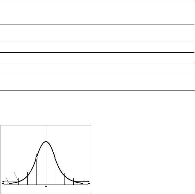
To determine the placement accu-
racy on SIPLACE machines, highly
precision glass components with
mounted structures are placed on
a dimensionally accurate glass
mapping plate. The results are sta-
tistically evaluated and presented
as a Gaussian standard distribu-
tion. In the case of the 12-Nozzle
Collect & Place Head the place-
ment accuracy is ± 90 µm at a sta-
tistical reliability of 4 sigma. In
other words, of one million placed
components, 60 are outside the
specified tolerance (= 60 dpm). If
the accuracy value ± 90 µm is di-
vided by the sigma value 4, the re-
sult is the standard deviation S of 1
sigma = ± 22.5 µm.
A machine capability analysis is
conducted for each machine ac-
ceptance test.
Machine Criteria:
Placement Accuracy
Technical Data Gantry
Drive Brushless AC
Temperature Controlled Motor (X-axis)
Linear drive (Y-axis)
Position measuring system
(X/Y)
Linear scales
Resolution of X-/Y-axis 1 µm
Speed of X-axis max. 2 m/s
Speed of Y-axis max. 2.5 m/s
Placement Accuracy see table on page 6
Standard Deviation – dpm
-4
σ
-3
σ
-2
σ
σ
x
σ
2
σ
3
σ
4
σ
2700 dpm
60 dpm
P Point of Inflection