西门子SIPLACE HS 50-设备参数_EN.pdf - 第26页
24 ➀ 12-Nozzle Collect & Place Head ➁ X-/Y-Gantry System ➂ Fixed Component Supply ➃ Fixed PC B Description In addition to c orrect positioning, placement re liability is impor tant. On the SIPLACE HS-50 this is en- s…
23
Description
Various factors contribute to the
placement accuracy of the
SIPLACE HS-50 machine, e.g., the
stationary PCB during the place-
ment process. As no accelerations
are acting on the placed compo-
nents, their position continues un-
changed. The PCB moves in and
out at a coordinated speed which
is automatically reduced just be-
fore the nominal position is
reached.
A further guarantee for long-term
high placement accuracy is the po-
sition recognition of the axes of
the gantry and placement head by
means of optical scanning by in-
cremental encoders. Revolving star
and segments of the Collect &
Place Head are positioned by
means of high-resolution glass in-
cremental panels. The X- and Y-
axes are positioned with the help
of the linear scales on each gantry
axis.
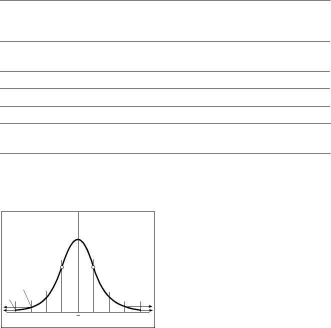
To determine the placement accu-
racy on SIPLACE machines, highly
precision glass components with
mounted structures are placed on
a dimensionally accurate glass
mapping plate. The results are sta-
tistically evaluated and presented
as a Gaussian standard distribu-
tion. In the case of the 12-Nozzle
Collect & Place Head the place-
ment accuracy is ± 90 µm at a sta-
tistical reliability of 4 sigma. In
other words, of one million placed
components, 60 are outside the
specified tolerance (= 60 dpm). If
the accuracy value ± 90 µm is di-
vided by the sigma value 4, the re-
sult is the standard deviation S of 1
sigma = ± 22.5 µm.
A machine capability analysis is
conducted for each machine ac-
ceptance test.
Machine Criteria:
Placement Accuracy
Technical Data Gantry
Drive Brushless AC
Temperature Controlled Motor (X-axis)
Linear drive (Y-axis)
Position measuring system
(X/Y)
Linear scales
Resolution of X-/Y-axis 1 µm
Speed of X-axis max. 2 m/s
Speed of Y-axis max. 2.5 m/s
Placement Accuracy see table on page 6
Standard Deviation – dpm
-4
σ
-3
σ
-2
σ
σ
x
σ
2
σ
3
σ
4
σ
2700 dpm
60 dpm
P Point of Inflection
24
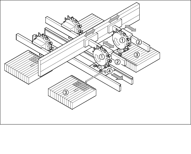
➀ 12-Nozzle Collect & Place Head
➁ X-/Y-Gantry System
➂ Fixed Component Supply
➃ Fixed PCB
Description
In addition to correct positioning,
placement reliability is important.
On the SIPLACE HS-50 this is en-
sured through a number of control
functions, such as vacuum checks
and component vision testing dur-
ing the placement sequence.
Out of tolerance components are
rejected, placed on the repair list
and automatically processed during
a repair cycle. An offset in the po-
sition of the PCB relative to the
conveyor system (PCB vision) and
an offset of the X-axis, Y-axis or ro-
tation of the component relative to
the midpoint of the nozzle (com-
ponent vision) trigger an immedi-
ate correction to ensure placement
accuracy.
Since the PCB is fixed, the com-
ponents remain in the exact posi-
tion they are placed. The stationary
component table ensures a precise
pick up. Options, such as the
component bar code scanner,
can be added to further enhance
reliability.
Placement errors
Placement errorsPlacement errors
Placement errors
Errors that occur after the compo-
nent has been placed on the PCB.
They include:
§ Component is missed on PCB
§ Too many components on PCB
§ Components not placed prop-
erly on PCB
§ Components placed while
standing on edge
Machine Criteria:
Placement Reliability
Placement Principle SIPLACE HS-50
25
Description
Slight distortions of the gantry
axes cannot always be avoided de-
spite the highly stable machine
frame. With the aid of the mapping
approach, the high placement pre-
cision of the machine is maintained
throughout its service life.
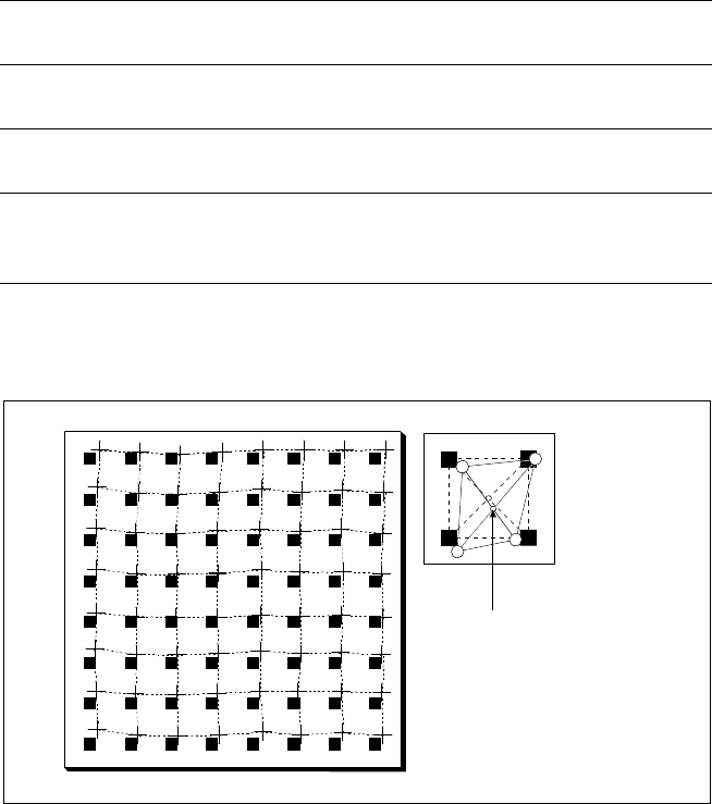
With this calibrating procedure,
which can be conducted quickly
and easily, the PCB camera recog-
nizes the fiducials on a mapping
calibration plate placed in its oper-
ating area. This board has highly
accurate marks on it. Any distor-
tions are located by comparing the
nominal grid on the mapping board
with the actual grid ”drawn” by
the placement head. These distor-
tions are then considered when
calculating all further positioning of
the X-/Y-axis and are thus compen-
sated for.
Machine Criteria:
Mapping (Option)
Nominal Grid of Mapping Plate and Actual Grid with
Deviations Due to Gantry
Corrected
Position
Technical Data
Dimensions of the mapping
test plate
520 x 460 mm
2
(for single conveyor)
520 x 215 mm
2
(for dual conveyor)
Number of measurement
points
13 x 11 (standard resolution)
26 x 21 (high resolution)
Ambient temperature during
calibration + 20° ± 3°C
Components of the option Test plate (special glass)
Calculation data (disk)
Case for secure storage