西门子SIPLACE HS 50-设备参数_EN.pdf - 第4页
2 Very High Speed SMD Placement System SIPLACE HS-50 SIPLACE HS-50
1
Subject to change
without notice.
Edition 5
1001-HS50-300-e
Order No
E80002-P104-A402-X-7600
Machine Description 3
Line Design 4
Placement Heads 5
Placement Accuracy
Component Range
12-Nozzle Collect & Place Head for Very High Speed
Component Placement
Nozzle Changer for 12-Nozzle Collect & Place Head (Option)
PCB Conveyor 9
Single Conveyor
Dual Conveyor
Ceramic Substrate Centering (Option)
PCB Bar Code for Production-Controlled Manufacturing (Option)
Component Supply 13
Changeover Table
Tape Feeder
Bulk Case Feeder
Guard for Feeder Locations
Component Bar Code Scanner for Set-Up and
Refill Check (Option)
Vision Sensor Technology 18
PCB Vision Module
PCB Position Recognition
Bad Board Recognition
Position Recognition of Feeder
Algorithms to Determine the X-/Y-Position and the
Placement Angle
Standard Component Vision Modules for 12-Nozzle
Collect & Place Head
Machine Criteria 23
Placement Accuracy
Placement Reliability
Mapping (Option)
SIPLACE Software Architecture 26
Line Computer / Station Computer
Technical Data 27
Signal Interfaces
Connections
Dimensions and Set-Up Conditions
Transporting and Commissioning
Possible Machine Configuration 32
Very High Speed SMD Placement System
SIPLACE HS-50
2
Very High Speed SMD Placement System
SIPLACE HS-50
SIPLACE HS-50

3
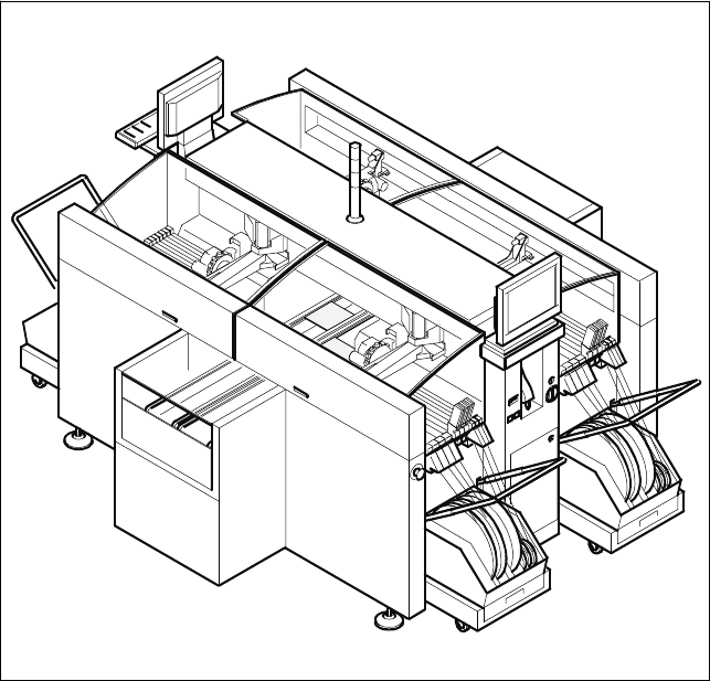
Description
The SIPLACE HS-50 very high-
speed SMD placement system
combines very high placement
speed with both accuracy and
flexibility. In contrast to classic
chipshooters, a Collect & Place
procedure is applied here.
SIPLACE HS-50 machines are
equipped with four X-Y-main gan-
tries. Each gantry features a star-
shaped 12-Nozzle Collect & Place
Head. The placement heads alter-
nately pick up components from a
stationary feeder bank and place
these components on the station-
ary PCB.
This has distinct advantages:
§ Component tapes of all sizes
can be replenished by splicing a
new reel of components to the
end of a depleting reel. This eli-
minates machine stoppage due
to component replenishment.
§ Stationary, vibration-free feeders
ensure a reliable pick-up of even
the smallest components (e.g.,
0201 and 0402 chips).
§ Thanks to the flexibility of the
12-Nozzle Collect & Place Heads
– whose ideal nozzle set-up is
automatically specified – the
travel can be minimized and the
sequence of placement opti-
mally adjusted.
§ Populating a stationary PCB
also prevents components from
shifting during placement.
Speed coupled with economic ef-
ficiency and set-up reliability is the
SIPLACE HS-50´s recipe for suc-
cess. Components are pre-picked
as the PCB is transported into the
placement area. Path-optimization
ensures high performance: While
one Collect & Place Head is placing
components, the second head is
picking up the next series of com-
ponents to be placed.
The following options are available
for the SIPLACE HS-50:
§ Additional changeover tables
enables the reduction of job set-
up time increasing machine utili-
sation.
§ Dual Conveyor eliminates the
non-productive PCB loading
times thus increasing machines
operating efficiency.
§ Automatic nozzle changers for
both changeover and storage of
nozzles.
§ PCB Barcode Reader used for
product controlled production
changeover.
§ Component Bar Code Scanner
used for feeder set-up verifica-
tion.
§ To achive the best placement
quality we recommend to order
an 0201 enhance kit.
§ Ceramic Substrat Centering
Machine Description
Technical Data
Type of placement head 12-Nozzle Collect & Place Head
Number of gantries 4
Benchmark placement rate
a
50,000 cph
Component Range 0.6 x 0.3 mm
2
(0201) to 18.7 x 18.7 mm
2
Max. placement accuracy
(at 4 sigma)
a
90 µm
PCB dimensions (L x W)
Single conveyor
Dual conveyor
50 x 50 mm
2
to 368 x 460 mm
2
/
2" x 2" to 14.5" x 18"
(optional up to 610 mm length)
50 x 50 mm
2
to 368 x 216 mm
2
/
2" x 2" to 14.5" x 8.5"
(optional up to 610 mm length)
Feeding capacity 144 tracks, 8 mm tape
Component table Quick changeover table with integrated
wheels, reel holder and scrap bin,
Types of Feeder modules Tapes, Bulk Cases,
application-specific OEM feeders
Operating system Microsoft Windows / RMOS
Power 4 kW
Compr. air requirements 6.5 - 10 bar, 950 Nl/min, Tube ¾"
a) As defined in “Scope of Service and Delivery SIPLACE”.