西门子SIPLACE HS 50-设备参数_EN.pdf - 第28页
26 Description The UNIX line computer is as- signed the following interstation tasks: creation, revi sion and man- agement of placement programs, job data and component and GF li- braries; automatic, optimized gen- erati…
25
Description
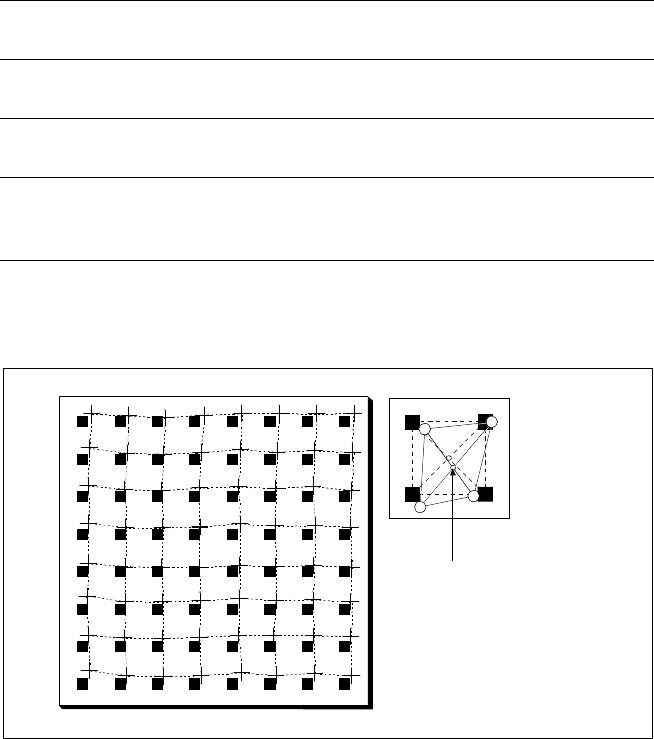
Slight distortions of the gantry
axes cannot always be avoided de-
spite the highly stable machine
frame. With the aid of the mapping
approach, the high placement pre-
cision of the machine is maintained
throughout its service life.
With this calibrating procedure,
which can be conducted quickly
and easily, the PCB camera recog-
nizes the fiducials on a mapping
calibration plate placed in its oper-
ating area. This board has highly
accurate marks on it. Any distor-
tions are located by comparing the
nominal grid on the mapping board
with the actual grid ”drawn” by
the placement head. These distor-
tions are then considered when
calculating all further positioning of
the X-/Y-axis and are thus compen-
sated for.
Machine Criteria:
Mapping (Option)
Nominal Grid of Mapping Plate and Actual Grid with
Deviations Due to Gantry
Corrected
Position
Technical Data
Dimensions of the mapping
test plate
520 x 460 mm
2
(for single conveyor)
520 x 215 mm
2
(for dual conveyor)
Number of measurement
points
13 x 11 (standard resolution)
26 x 21 (high resolution)
Ambient temperature during
calibration + 20° ± 3°C
Components of the option Test plate (special glass)
Calculation data (disk)
Case for secure storage
26
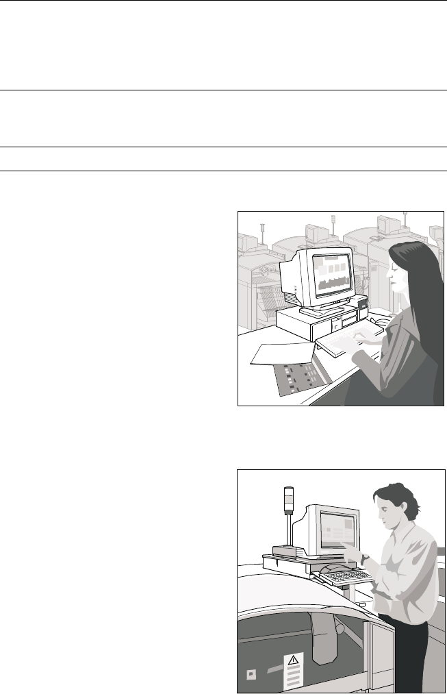
Description
The UNIX line computer is as-
signed the following interstation
tasks: creation, revision and man-
agement of placement programs,
job data and component and GF li-
braries; automatic, optimized gen-
eration and administration of ma-
chine set-ups (set-up optimization,
set-up editors, optional set-up se-
quence optimization); determina-
tion of optimized travel for gantry
and nozzle assignments of the
Collect & Place Heads; control and
supply of data to SIPLACE ma-
chines in a line; calculation, storage
and display of machine and oper-
ating data; data backup on built-in
magnetic tape drive.
The Windows station computer in
conjunction with the machine con-
troller with its realtime capability
performs the following jobs: digital
control of the machine gantry sys-
tems; control of PCB input and
output and of PCB transport; moni-
toring functions, handling of mal-
functions and output of error mes-
sages (including Help system);
ensuring the optimal quality of the
placement process; optional load-
ing control by means of compo-
nent bar code and optional place-
ment program change by means of
PCB bar code.
For more detailed information
please see “SIPLACE Software
Specification”.
SIPLACE Software Architecture:
Line Computer / Station Computer
Functions
Line computer Programming
Optimization
Line control
Line monitoring
Data management
Station computer Machine control
Machine monitoring
Machine operation
Softwareversion From 501.xx
Line Computer
Station Computer
27
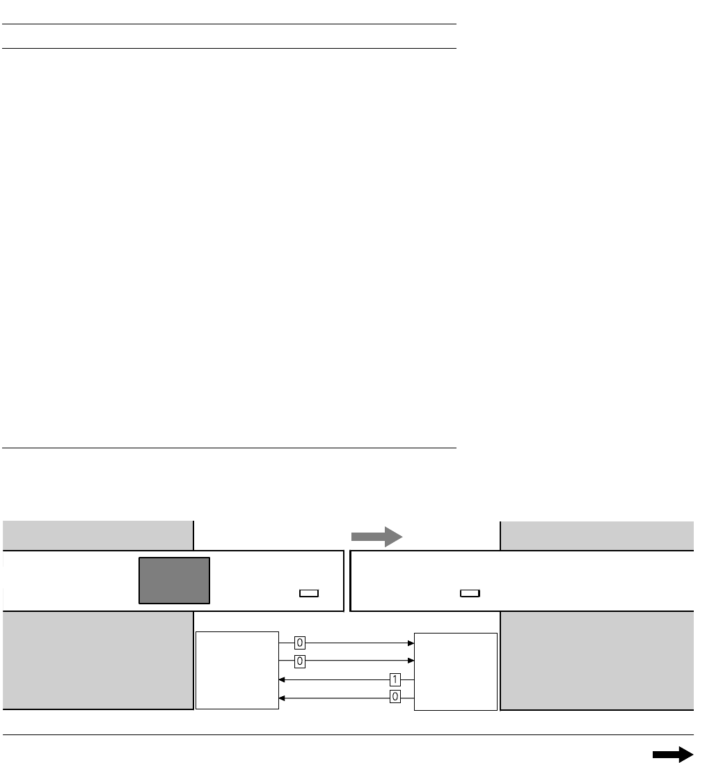
1. After switching-on the station
Technical Data:
Signal Interfaces
Signal Interface (20-Pin Ribbon Cable Connector)
to upstream station x3 to downstream station x4
Pin 13 GND 24 V Pin 10 Reserved
Pin 14 Arrived Pin 9 Reserved
Pin 15 Permission Pin 8 Reserved
Pin 19 Request Pin 4 +30 V DC
unsaturated
Pin 20 GND 24 V for request / re-
leased (contact separation)
Pin 5 GND 24 V
Pin 18 Released Pin 6 +24 V DC
Pin 12 Trouble signal loop Pin 11 Trouble signal loop
Pin 11 Pin 12
Pin 3 +24 V DC Pin 15 Permission
Pin 2 GND 24 V Pin 13 GND 24 V for per-
mission / arrived
(contact separation)
Pin 1 +30 V DC unsaturated Pin 14 Arrived
Pin 8 Reserved Pin 18 Released
Pin 9 Reserved Pin 19 Released
Pin 10 Reserved Pin 20 GND 24 V
Requirement
Delivery
Permission
Receiva
l
Requirement
Delivery
Permission
Receiva
l
Transport Direction
Conveyor Section 1
PCB
Sensor
PCB
Sensor
Conveyor Section 2
Station n
transports
PCB
to delivery
Station n+1
is ready to
receive PCBs
Conve
y
or 1 is On Conve
y
or 2 is Off