TM1629_TM1630_TM1631.The explanation document of the parameters on simplified GUI.pdf - 第14页
SMT Software Engineering Group IM Operations Y AMAHA MOT OR CO.,L TD MDOC-SO FT50035 14/34 7. 2Ends 7.1. C heck Direction Suitable f or determ ining t he directi on of com ponents with 2 leads, such as 2-…
SMT Software Engineering Group
IM Operations
YAMAHA MOTOR CO.,LTD
MDOC-SOFT50035
13/34
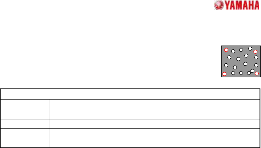
6. Flip Chip
6.1. Simple High Speed
Suitable for components with randomly arrayed balls.
A ball information setting is required which includes at least 2 reference ball
pairs (near 4 corners). Ball detection occurs by contour tracing.
Particular parameters
Cut Outer Noise
Cut Inner Noise
The amount of application of the noise cut is specified. In order to add
processing to the image, if it applies too much, quality of image will deteriorate.
Object Type It is specified whether an object is “White” or “Black”.
Noise Cut Order
The execution order of noise cuts is specified. Generally, the influence of what is
performed previously is large.
SMT Software Engineering Group
IM Operations
YAMAHA MOTOR CO.,LTD
MDOC-SOFT50035
14/34
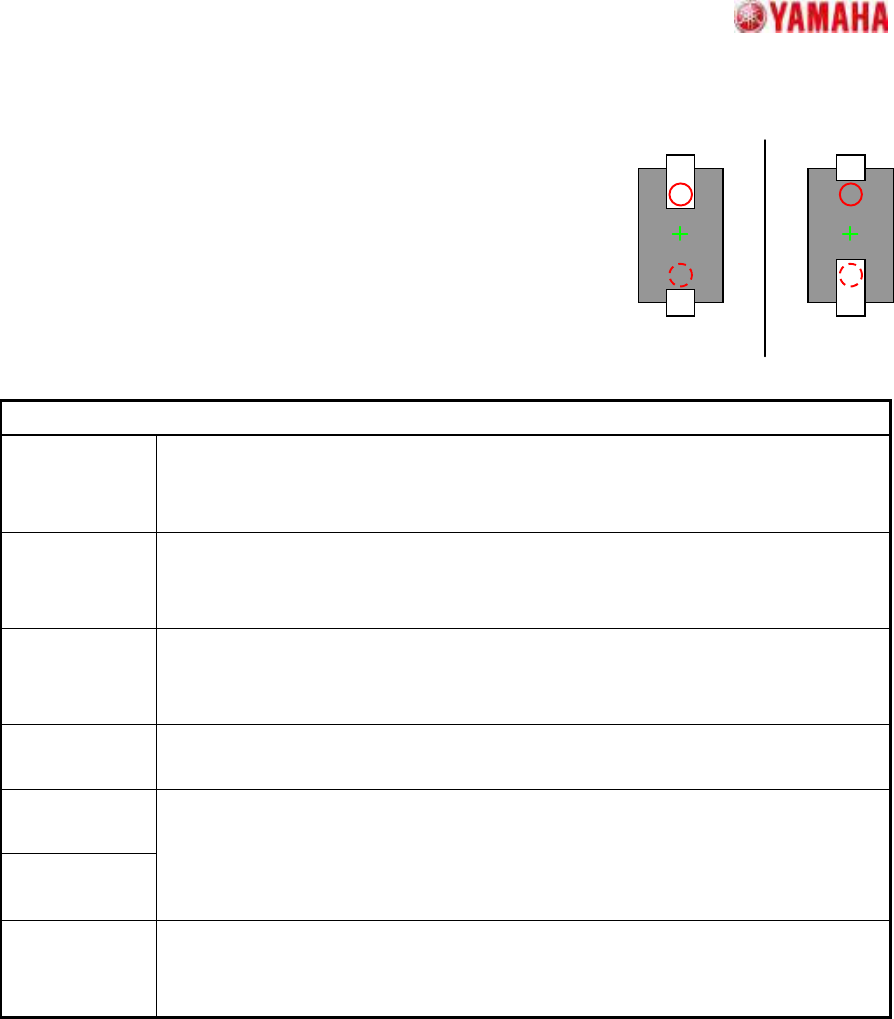
7. 2Ends
7.1. Check Direction
Suitable for determining the direction of components with 2 leads,
such as 2-terminal diodes.
A direction judgment is made by comparing the average
brightness of the specified circle area with a 180 degrees opposing
circle area. Suitable where a polarity mark, etc., exists on the
recognition face.
Particular parameters
Check Type When it is expected that the brightness of the specified circle will be brighter than
the brightness of a rotation symmetry position, “White” is specified. Else “Black” is
specified.
Check
Direction
The direction at which a direction judging is performed is specified.
In distinguishing 0 and 180 degrees, “2 Angle” is specified. In distinguishing 0, 90,
180, and 270 degrees, “4 Angle” is specified.
Min.
Brightness
Difference
The difference in the average brightness of detection circles being checked in
order to differentiate the directions must be larger than this value, or an error will
occur. If 0, 50 will be set.
Direction Mark
Diameter (mm)
The diameter of the circle where brightness is measured is specified.
Direction Mark
Center X
Direction Mark
Center Y
The center position of the circle where brightness is measured is specified.
(Origin: The component center)
Check Many
Adsorption
It confirms whether excessive components exist. When the “Check” is specified, it
becomes an error if excessive edges exist around the detected component.
*Cannot use this parameter on VGOS V2.xx and YGOS V2.xx.
+0
゚
+180
SMT Software Engineering Group
IM Operations
YAMAHA MOTOR CO.,LTD
MDOC-SOFT50035
15/34
OK NG
A
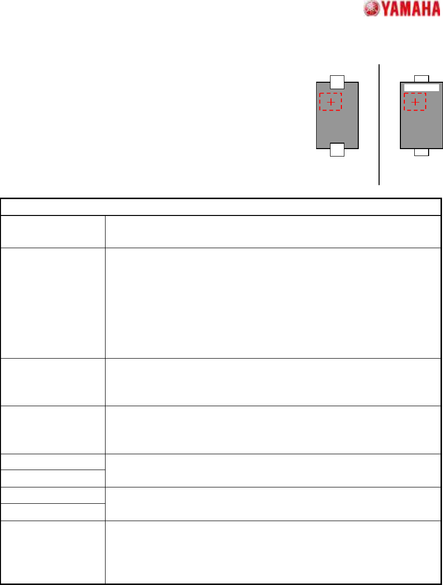
7.2. Check Upside-Down
Suitable for top/bottom judgments at components with 2 leads,
such as 2-terminal diodes.
The component top/bottom judgment occurs by checking the
brightness variation (dispersion) at the specified judgment area.
Suitable when printed characters, etc., are present at the mold area
of the pickup face.
Particular parameters
Threshold of 3-sigma
The threshold of the brightness variation for check is specified. The value
specified here is compared with the brightness variation in the check area.
Threshold of Average
Usually, “0” is specified. A superfluous judging may be prevented by setting
up values other than “0”. When a value other than “0” is set up, It becomes
an error when the following three conditions are fulfilled.
1. “Dispersion” is specified as “NG Condition”.
2. The brightness variation in the check area is over the value specified
as “Threshold of 3-sigma”.
3. The average brightness in the check area is larger than this.
Check-area Offset
Enable
When “Enable” is specified, the check area is moved according to the value
specified as “Check-area Offset”. When “Disable” is specified, the check
area is set as the center of the component.
NG Condition When “Dispersion” is specified, it becomes an error when the measured
value is larger than the value specified as “Threshold of 3-sigma”
parameter. In the case of “Non Dispersion”, it becomes the contrary.
Check-area Size X
Check-area Size Y
The size of the check area is specified.
Check-area Offset X
Check-area Offset Y
Offset of the check area is specified.
(Origin: The component center)
Check Many
Adsorption
It confirms whether excessive components exist. When the “Check” is
specified, it becomes an error if excessive edges exist around the detected
component.
*Cannot use this parameter on VGOS V2.xx and YGOS V2.xx.