TM1629_TM1630_TM1631.The explanation document of the parameters on simplified GUI.pdf - 第25页
SMT Software Engineering Group IM Operations Y AMAHA MOT OR CO.,L TD MDOC-SO FT50035 25/34 13. A s Mark 13.1. Mark Line Suitable f or rectangular com ponents lik e that shown in the fi gure, where part of…
SMT Software Engineering Group
IM Operations
YAMAHA MOTOR CO.,LTD
MDOC-SOFT50035
24/34
12. Special
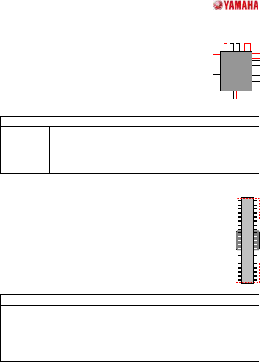
12.1. Side Lead Fitting
Suitable for components with leads of different shapes and pitches in the
same direction.
Setting is possible for up to 4 directions x 2 groups. When the end lead is
detected, the positional relationship of the leads is checked, and the pairing
that most closely matches the component definition is selected in order to
increase the recognition rate.
Particular parameters
Excessive Lead
Check
If “Check” is specified, when the component whose lead pitch and width are
same and which have excessive leads is supplied, it becomes an error. In “No
Check”, the check is not performed.
Lead Length
Tolerance (mm)
If the difference between the straight line which is applied at the tip of leads and
each lead tip is larger than the value set up here, it becomes an error.
12.2. Long Connector
Suitable for components where the lead ends in the center vicinity cannot be detected
properly due to the pickup clip, etc
Although the lead quantity check, etc., occurs in the usual manner, only the specified
both-ends lead quantity is used for positioning.
Particular parameters
Detecting Numbers
of side lead
The lead number used for positioning is specified. The number per end and
side are specified. (If “5” is specified, it becomes what is shown by the red
frame of the above figure.)
Excessive Lead
Check
If “Check” is specified, when the component whose lead pitch and width are
same and which have excessive leads is supplied, it becomes an error. In
“No Check”, the check is not performed.
SMT Software Engineering Group
IM Operations
YAMAHA MOTOR CO.,LTD
MDOC-SOFT50035
25/34
13. As Mark
13.1. Mark Line
Suitable for rectangular components like that shown in the figure,
where part of the contour may extend beyond the detection
range.
When part of the contour extends beyond the detection range,
the center and angle are estimated based on the remaining sides.
Suitable for components with contours that contain uneven sections,
because the scan line position can be freely specified.
Particular parameters
Detect
Direction
The direction (which a projection does not generate) used for detection is specified.
Usually, “Auto” is specified.
Right Line
Offset (mm)
The distance of “A” in the figure is specified. When
“0” is specified, one fourth of detected X size is
applied.
Right Center
Offset (mm)
The distance of “B” in the figure is specified. When
“0” is specified, one fourth of detected Y size is
applied.
Left Line
Offset (mm)
The distance of “C” in the figure is specified. When
“0” is specified, one fourth of detected X size is
applied.
Left Center
Offset (mm)
The distance of “D” in the figure is specified. When
“0” is specified, one fourth of detected Y size is
applied.
A
B
C
D
SMT Software Engineering Group
IM Operations
YAMAHA MOTOR CO.,LTD
MDOC-SOFT50035
26/34
13.2. 2 Objects
Suitable for components with 2 distinctive terminals.
Accommodates complex shape terminals because terminal extraction is based on
the surface area. The component center is the average center of gravity position of
the 2 terminals, and the angle is the tilt of a straight line which connects the 2 center of gravity positions.
Particular parameters
Method of Auto
Binarize
The method of binarizing is specified. This parameter is effective only
when the threshold is 0.
Brightness
Distinction
It searches for the threshold which improves separation of
white and black most automatically. It is suitable when the
brightness difference of a terminal section and a base
section is big.
Area Size
Distinction
A threshold is determined that the area judged as white
equal to the area defined as terminals. It is suitable when
there is nothing to reflect in addition to terminals.
Pickup by Terminal
Shape
When “Use” is specified, form evaluation is performed at the time of the
terminal extraction. When “Not Use”, only area is evaluated.
Detection Angle Direction check in case terminals’ size and form differs from each other is
specified. When “+-90 Deg” is specified, direction check is not performed.
When “+-180Deg”, it is performed.
Method of Size Check The size check method of the circumscription rectangle of the terminals
obtained by recognition is specified. When “Body Size” is specified, it is
compared with the outside dimension of part data. When “Terminal
Circumscribed Size” is specified, it is compared with the circumscription
rectangle of the terminal sections of part data.
Binary Level Correction
This parameter is effective only when the “Threshold” is 0, and when
“Method of Auto Binarize” is “Area Size Distinction”. When there are
portions which look white in addition to the terminals for detection, the
rate of the portion to the terminal area is specified.
Terminal Width (mm)
Terminal Length (mm)
The size of terminals is specified. If “0” is set as “Terminal Length”,
terminal shape becomes circular and “Terminal Width” is a diameter.
Find PosY (mm) The terminal’s center of gravity in a perpendicular direction is specified.
(Origin: The center of component)