TM1629_TM1630_TM1631.The explanation document of the parameters on simplified GUI.pdf - 第27页
SMT Software Engineering Group IM Operations Y AMAHA MOT OR CO.,L TD MDOC-SO FT50035 27/34 13.3. 4 Objects Suitable for rec tangular components with t erminals at the 4 corner s. Positionin g occurs using…
SMT Software Engineering Group
IM Operations
YAMAHA MOTOR CO.,LTD
MDOC-SOFT50035
26/34
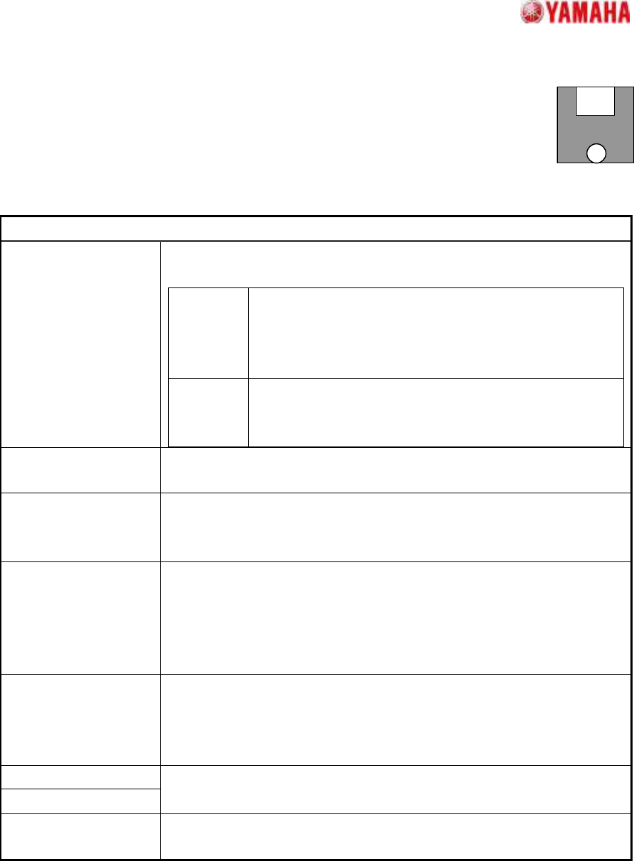
13.2. 2 Objects
Suitable for components with 2 distinctive terminals.
Accommodates complex shape terminals because terminal extraction is based on
the surface area. The component center is the average center of gravity position of
the 2 terminals, and the angle is the tilt of a straight line which connects the 2 center of gravity positions.
Particular parameters
Method of Auto
Binarize
The method of binarizing is specified. This parameter is effective only
when the threshold is 0.
Brightness
Distinction
It searches for the threshold which improves separation of
white and black most automatically. It is suitable when the
brightness difference of a terminal section and a base
section is big.
Area Size
Distinction
A threshold is determined that the area judged as white
equal to the area defined as terminals. It is suitable when
there is nothing to reflect in addition to terminals.
Pickup by Terminal
Shape
When “Use” is specified, form evaluation is performed at the time of the
terminal extraction. When “Not Use”, only area is evaluated.
Detection Angle Direction check in case terminals’ size and form differs from each other is
specified. When “+-90 Deg” is specified, direction check is not performed.
When “+-180Deg”, it is performed.
Method of Size Check The size check method of the circumscription rectangle of the terminals
obtained by recognition is specified. When “Body Size” is specified, it is
compared with the outside dimension of part data. When “Terminal
Circumscribed Size” is specified, it is compared with the circumscription
rectangle of the terminal sections of part data.
Binary Level Correction
This parameter is effective only when the “Threshold” is 0, and when
“Method of Auto Binarize” is “Area Size Distinction”. When there are
portions which look white in addition to the terminals for detection, the
rate of the portion to the terminal area is specified.
Terminal Width (mm)
Terminal Length (mm)
The size of terminals is specified. If “0” is set as “Terminal Length”,
terminal shape becomes circular and “Terminal Width” is a diameter.
Find PosY (mm) The terminal’s center of gravity in a perpendicular direction is specified.
(Origin: The center of component)
SMT Software Engineering Group
IM Operations
YAMAHA MOTOR CO.,LTD
MDOC-SOFT50035
27/34
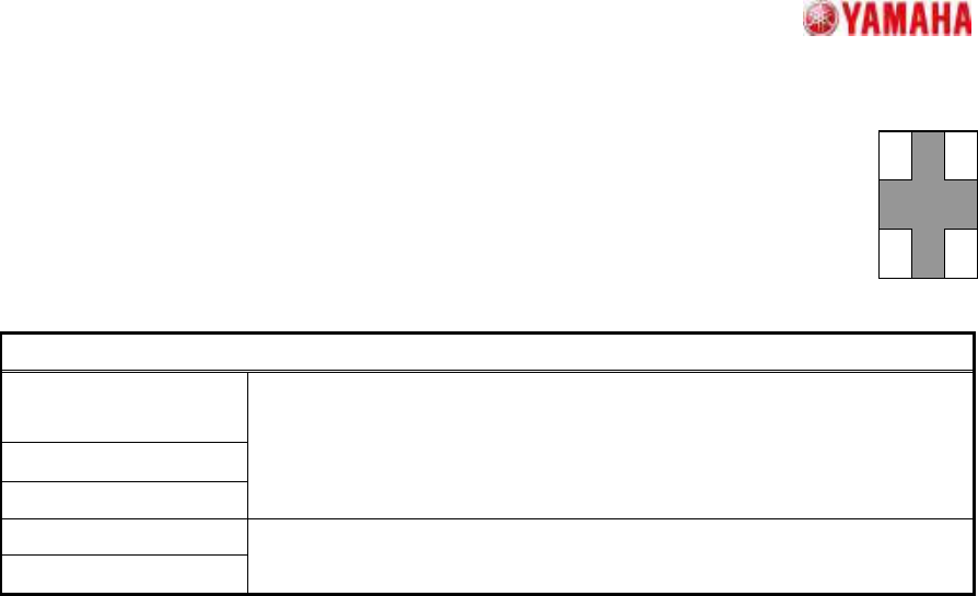
13.3. 4 Objects
Suitable for rectangular components with terminals at the 4 corners.
Positioning occurs using the terminal inner edges as a reference.
Particular parameters
Dir of Terminal Width
Check
Ruler Offset N/W
Ruler Offset S/E
(Reserved parameter)
Terminal Width (mm)
Terminal Length (mm)
The size of a terminal is specified.
SMT Software Engineering Group
IM Operations
YAMAHA MOTOR CO.,LTD
MDOC-SOFT50035
28/34
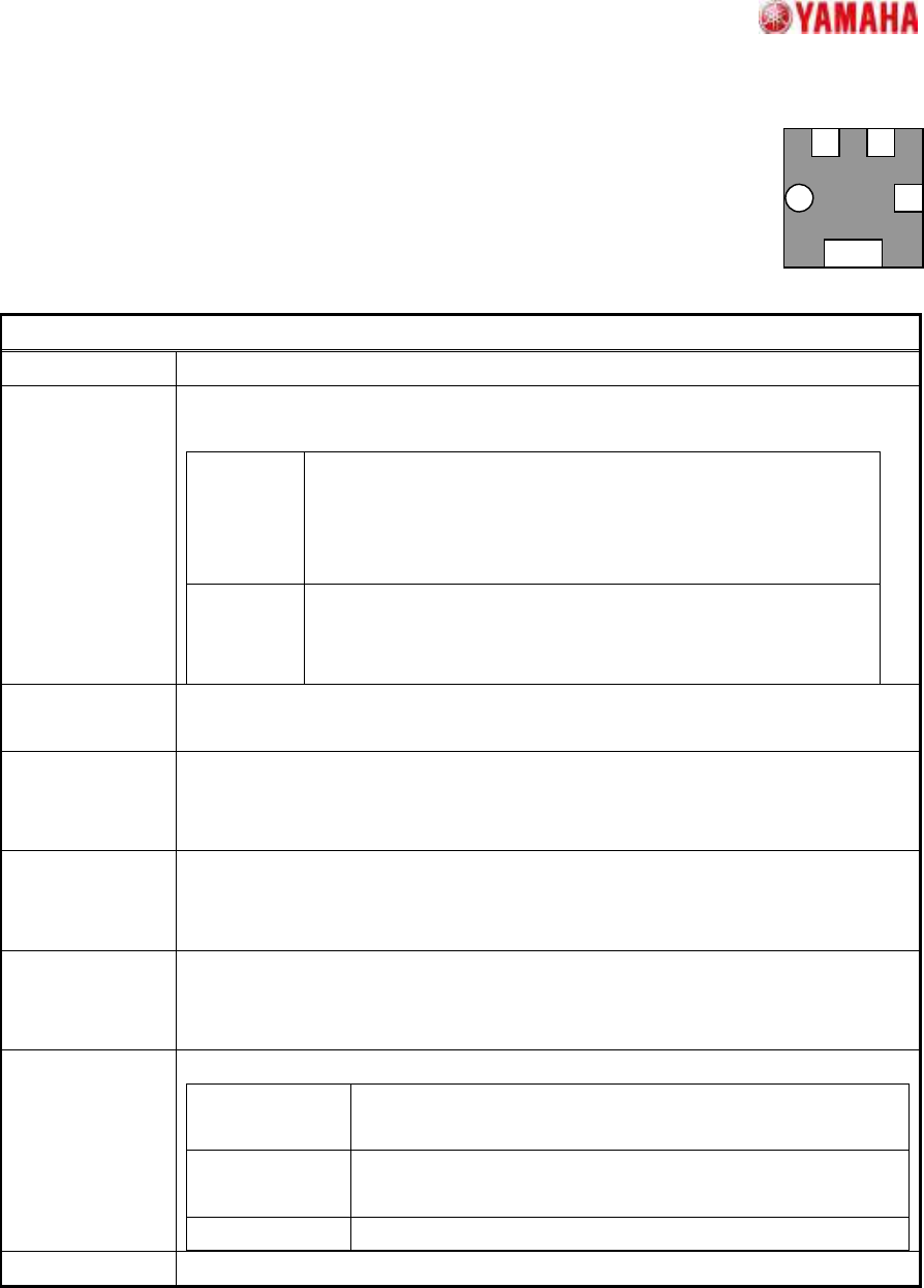
13.4. General
Suitable for components with 3 or more distinctive terminals.
Accommodates complex shapes because terminal selection is based on the
surface area.
Particular parameters
Check Pitch It is specified whether a strict pitch check is performed.
Method of Auto
Binarize
The method of binarizing is specified. This parameter is effective only when the
threshold is 0.
Brightness
Distinction
It searches for the threshold which improves separation of
white and black most automatically. It is suitable when the
brightness difference of a terminal section and a base section
is big.
Area Size
Distinction
A threshold is determined that the area judged as white equal
to the area defined as balls. It is suitable when there is
nothing to reflect in addition to terminals.
Check Terminal
Position
It is specified whether gap with the terminal position defined as the detected
terminal position is checked.
Terminal Pickup
Algorithm
The extraction method of corner terminals is specified. Usually, “Strictness” is
specified. If “Tolerance Synchronization” is specified, when extraction of corner
terminals is not stabilized, a recognition rate may improve.
Retry Trace In "On", it re-looks for the detection failure terminals based on the information of
the terminals which succeeded in detection. If "On", the recognition rate of low
contrast components may improve.
Best
Arrangement
Angle Detection
When specified except “Off”, recognition is performed using definition form of
either 0 and 90 degrees, or 0, 90, 180 and 270 degrees, and the angle of the
electrode arrangement nearest to the definition is looked for.
Center Detection
Algorithm
The calculation method of a component center is specified.
Circumscribed
Rectangle
The center of the rectangle circumscribed to the detected
terminals
Apex of
Rectangle
The center of the rectangle which consists of lines of the
component angle passing through the centers of each side
All Lead Center
The average of the center-of-gravity of all the terminals
Pre Threshold (Unused parameter)